
Suspension geometry refers to the arrangement and movement of suspension components that connect a vehicle’s wheels to its chassis. It determines how the wheels move when the suspension compresses, extends or responds to steering inputs.
The geometry of a suspension system directly affects vehicle handling, stability, tyre contact with the road and ride comfort. Even small changes in suspension dimensions or mounting positions can influence how a vehicle behaves during cornering, braking and acceleration.
Engineers consider suspension geometry during vehicle development to achieve the required balance between handling, stability and comfort.
What Are the Main Types of Suspension Geometry?
Different suspension designs use different arrangements of control arms, links, joints and mounting points. The choice depends on vehicle packaging, performance requirements and manufacturing constraints.
1. Double Wishbone Suspension
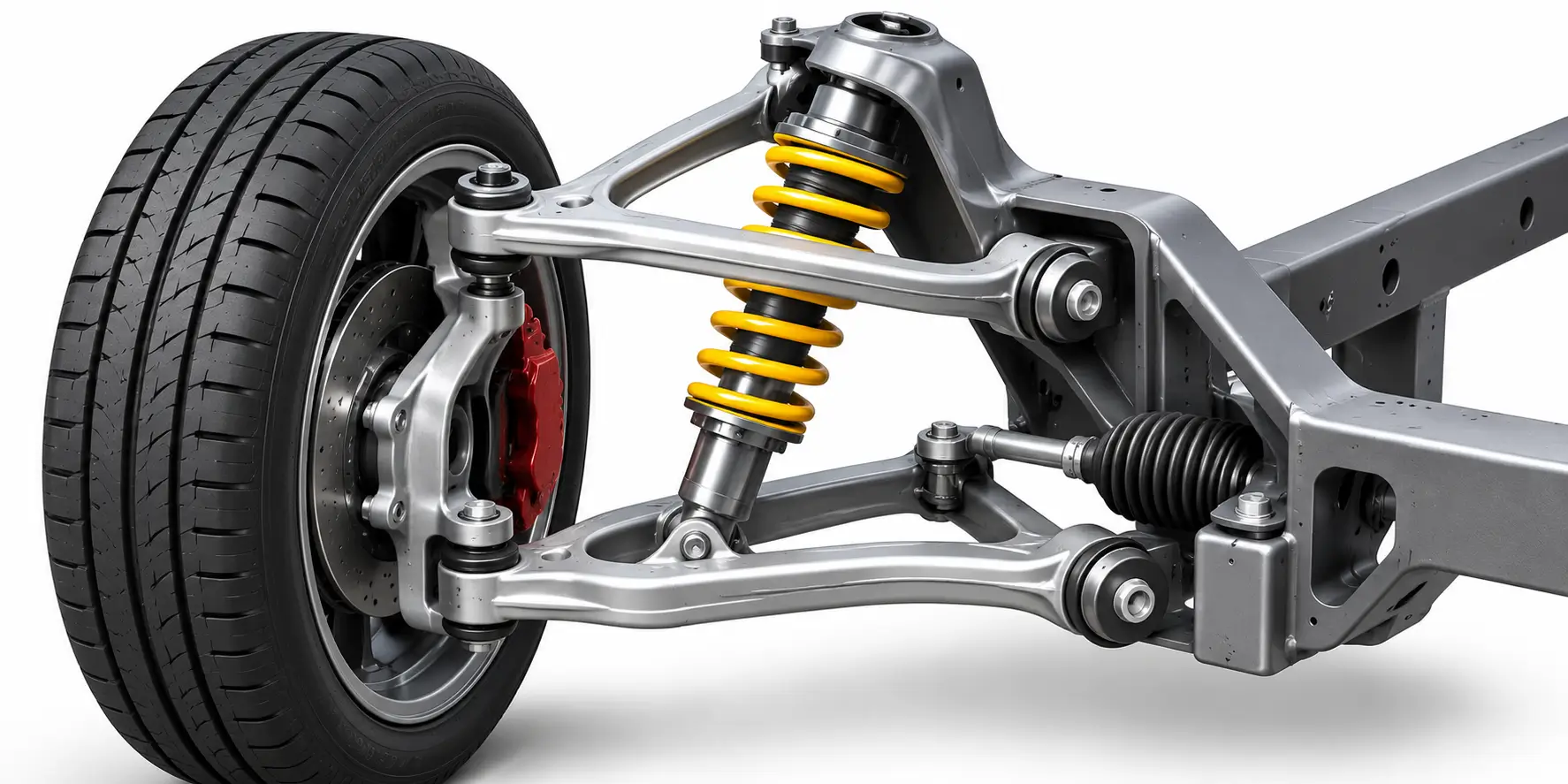
Double wishbone suspension uses two control arms, commonly called upper and lower wishbones, to connect the wheel assembly to the chassis.
The geometry allows engineers to control camber change and wheel movement during suspension travel. It is commonly used in performance cars and applications requiring precise wheel control.
2. MacPherson Strut Suspension
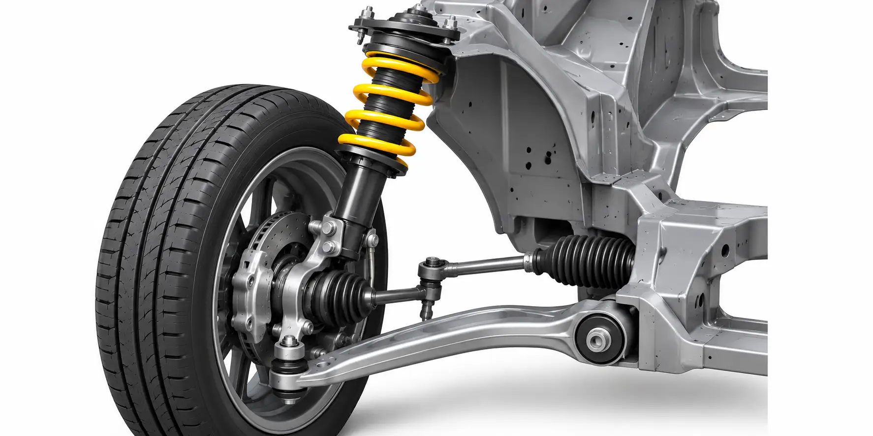
MacPherson strut suspension combines a spring and damper assembly with a lower control arm. It is widely used in passenger cars because of its relatively simple design and compact packaging.
Its geometry influences camber behaviour, steering characteristics and available engine compartment space.
3. Multi-Link Suspension
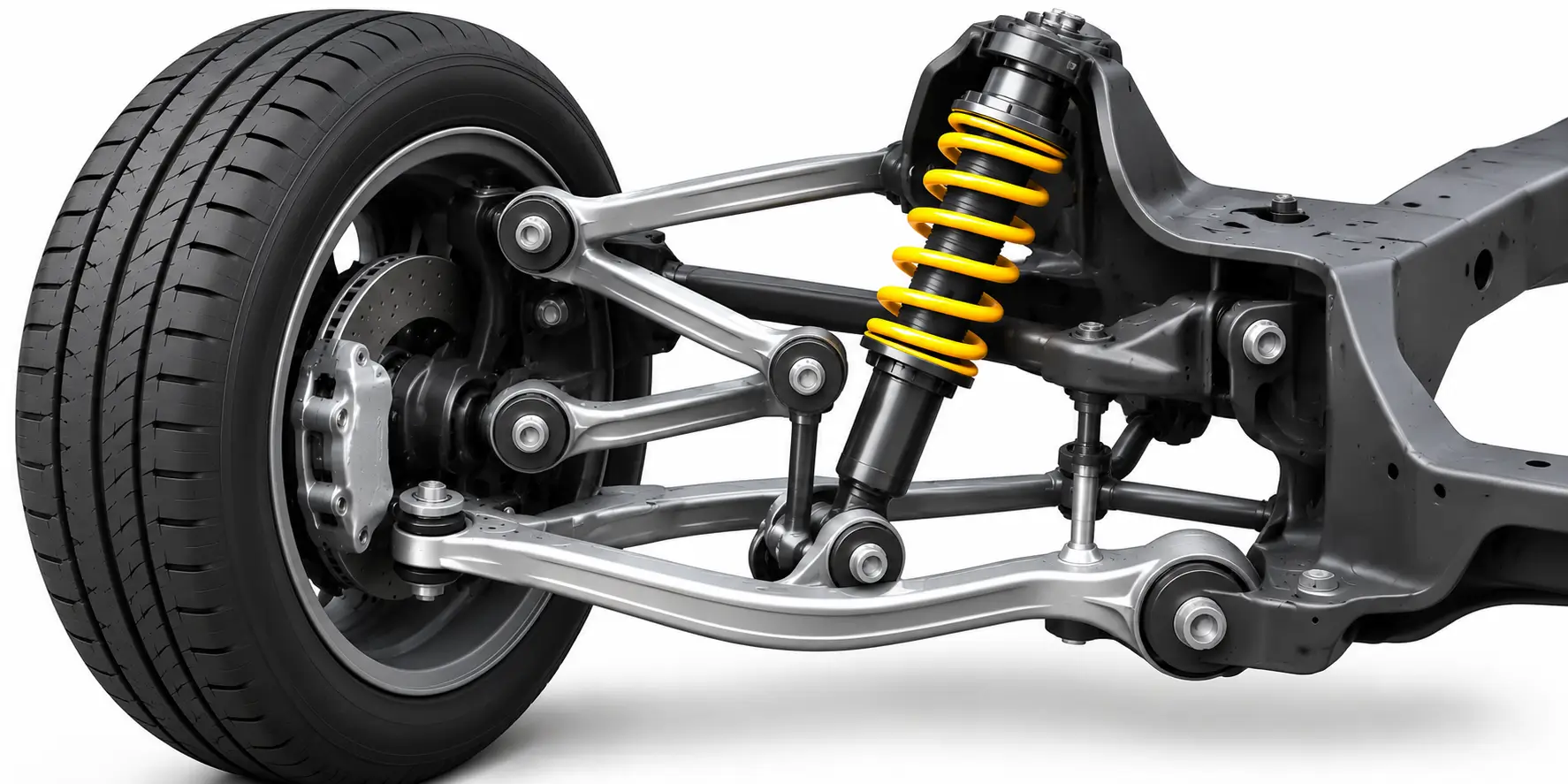
Multi-link suspension uses multiple links to control wheel movement. Each link influences specific aspects of wheel position and movement, giving engineers greater flexibility when tuning suspension behaviour.
It is commonly used in modern passenger cars and performance vehicles.
4. Trailing Arm Suspension
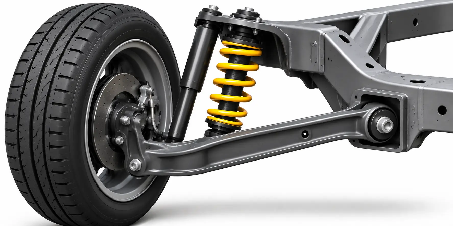
In a trailing arm suspension, the wheel is connected to the chassis through an arm that pivots around a mounting point ahead of the wheel.
The design controls the wheel’s movement along a defined path and is used in selected passenger cars and commercial vehicle applications.
What Are the Key Parameters of Suspension Geometry?
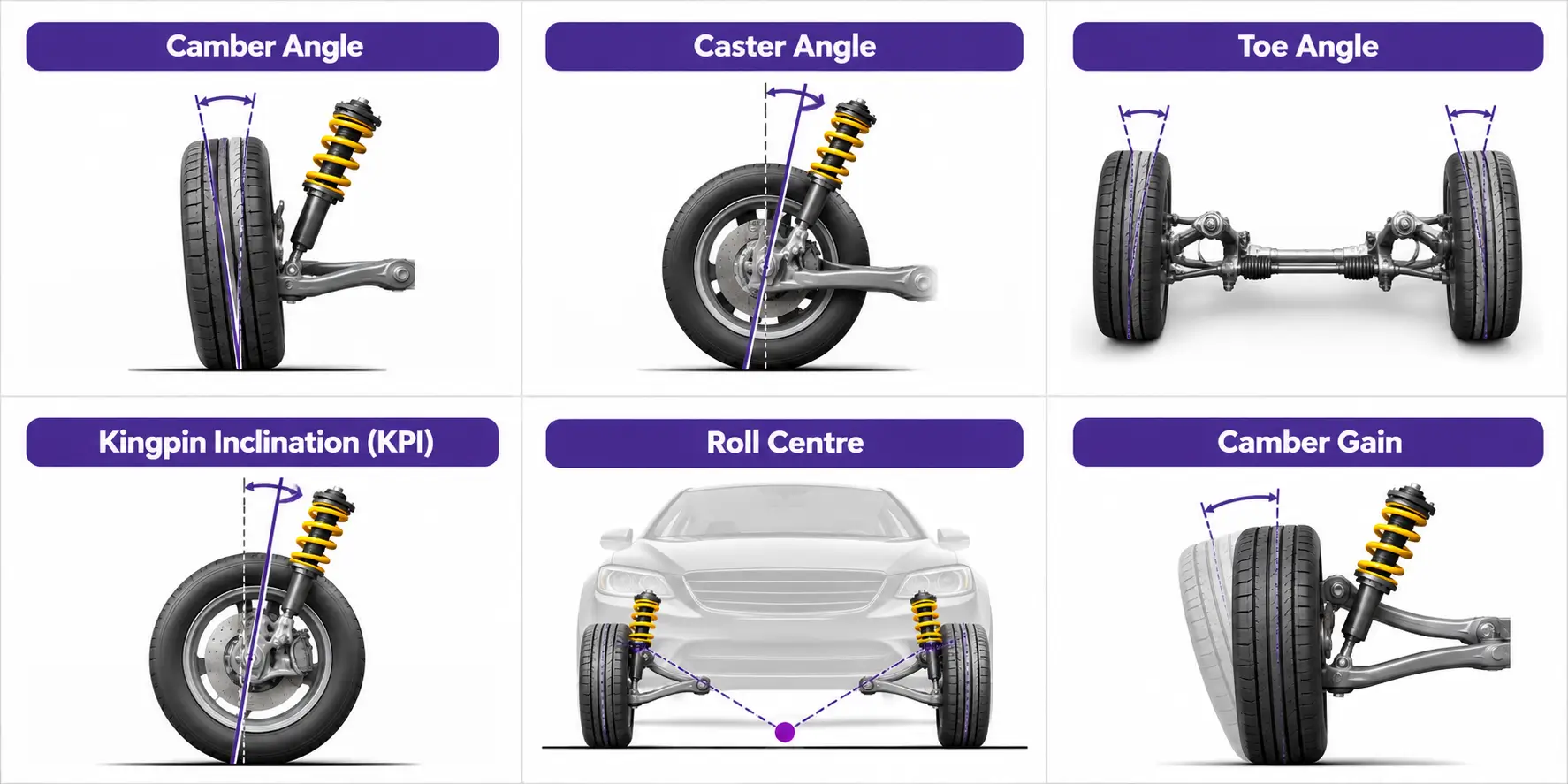
Suspension geometry is defined by several parameters that influence wheel position, steering response and vehicle handling.
Camber Angle: The inward or outward tilt of the wheel when viewed from the front of the vehicle. Camber affects tyre contact during cornering and influences tyre wear.
Caster Angle: The forward or backward inclination of the steering axis when viewed from the side. Caster influences steering stability, steering effort and self-aligning behaviour.
Toe Angle: The direction in which the wheels point when viewed from above. Toe affects straight-line stability, steering response and tyre wear.
Kingpin Inclination (KPI): The inward inclination of the steering axis when viewed from the front. It influences steering geometry, steering effort and wheel movement during steering.
Roll Centre: A theoretical point around which the vehicle body rolls during cornering. Its position affects lateral load transfer characteristics and suspension behaviour.
Camber Gain: The change in wheel camber as the suspension moves through its travel. It is an important consideration when maintaining tyre contact during cornering.
How Does Suspension Geometry Affect Vehicle Handling?
Suspension geometry influences how a vehicle responds to different driving conditions.
- Cornering: Camber behaviour and roll centre position influence tyre contact and lateral handling.
- Braking: Suspension movement can change wheel alignment and affect vehicle stability.
- Acceleration: Suspension geometry influences wheel movement and load distribution.
- Straight-Line Stability: Caster and toe settings affect steering stability and directional control.
- Tyre Wear: Incorrect alignment or unsuitable geometry can cause uneven tyre wear.
- Ride Comfort: Suspension link arrangement and wheel movement influence how road inputs are transmitted to the vehicle body.
What Should Engineers Consider When Designing Suspension Geometry?
Suspension geometry development requires careful consideration of wheel movement, component placement and vehicle requirements.
Important design considerations include:
- Wheel travel during compression and rebound.
- Camber and toe changes throughout suspension movement.
- Control arm lengths and mounting positions.
- Steering axis location and steering behaviour.
- Roll centre movement during cornering.
- Suspension component clearance and packaging.
- Load transfer and vehicle handling requirements.
Engineers must evaluate these parameters together because changing one suspension dimension can influence several other aspects of vehicle behaviour.
How Is Suspension Geometry Analysed?
Engineers use suspension kinematics and vehicle dynamics analysis to understand how suspension components and wheels move under different conditions.
Kinematic analysis evaluates wheel position, camber, toe and other geometric changes throughout suspension travel. Compliance analysis considers how component and bushing deflections influence wheel alignment under applied loads.
Simulation tools can also help evaluate suspension behaviour during steering, braking and cornering manoeuvres. This allows engineers to compare design alternatives and identify geometry changes that may improve vehicle handling.
Suspension Geometry Analysis at Caliber Technologies
Caliber Technologies provides suspension engineering and vehicle dynamics simulation support for automotive and commercial vehicle applications.
Our capabilities include suspension kinematics analysis, compliance steer analysis, load case development and simulation-based suspension optimisation. We help engineering teams evaluate wheel movement, alignment changes and suspension behaviour to support vehicle handling and design development.
To discuss your suspension design or analysis requirements, contact our engineering team.