A suspension component can pass a finite element analysis and still fail on the road. In many cases, the problem is not the finite element model itself. It is the load case used to represent what the component actually experiences during vehicle operation.
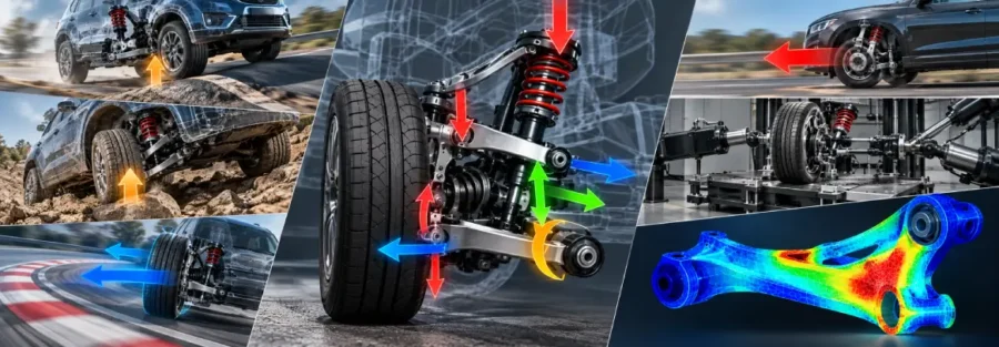
Suspension parts rarely see one simple vertical load. A control arm, knuckle, spring seat, axle attachment, or suspension bracket can experience a combination of vertical, longitudinal, and lateral forces as the vehicle accelerates, brakes, corners, crosses uneven roads, or encounters a pothole. The magnitude and direction of these forces also change with vehicle speed, payload, tire characteristics, suspension geometry, and road conditions.
For this reason, developing realistic suspension load cases is an important step between vehicle-level dynamics and component-level structural analysis. The objective is not simply to create large loads for an FEA model. It is to determine loads that represent the actual operating conditions of the vehicle and identify which events are most important for strength and durability.
Why Suspension Load Cases Matter
A suspension component is designed around the loads transmitted through its mounting points. If those loads are inaccurate, the resulting stress and fatigue predictions can be misleading.
A common approach is to apply a maximum vertical wheel load to a component and check the resulting stress. This can be useful during early design, but it does not capture many of the conditions that govern suspension durability.
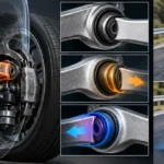
Consider a lower control arm during hard braking. The component may experience significant longitudinal force through the ball joint and bushings while also carrying vertical and lateral loads. During cornering, lateral tire forces can become dominant. During a pothole event, the vertical force can rise sharply over a short period. The critical location for each event may also be different.
A useful load-case development process therefore begins with the vehicle’s intended operating envelope rather than with the component itself.
Start With the Vehicle and Its Operating Conditions
The first step is to understand how the vehicle will actually be used.
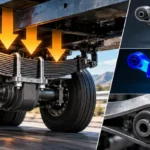
Engineers typically establish the important vehicle parameters, including mass, axle distribution, center-of-gravity location, wheelbase, track width, tire characteristics, suspension geometry, and intended payload. The operating environment is equally important. A passenger vehicle, heavy truck, trailer, and off-road vehicle can have very different suspension load requirements even when their components appear similar.
The design conditions may include normal operation as well as more severe events such as:
- Braking and acceleration
- Cornering
- Road bumps
- Pothole impacts
- Kerb or curb events
- Uneven road inputs
- Maximum payload operation
- Trailer or towing conditions
The important point is that these conditions should be defined before selecting the final FEA load cases. Otherwise, the structural analysis can become disconnected from the vehicle’s actual behavior.
How Multibody Dynamics Helps Generate Suspension Loads
Multibody dynamics is particularly useful when suspension forces need to be determined under realistic vehicle maneuvers.
A vehicle model can represent the suspension geometry, body and wheel masses, joints, bushings, tires, springs, dampers, and other relevant components. Engineers can then simulate different maneuvers and road inputs and extract the forces and moments transmitted through specific suspension connections.
This changes the question from:
“What load should be applied to this control arm?”
to:
“What force and moment does this control arm actually experience when the vehicle performs the required maneuver?”
That distinction is important.
For example, a vehicle dynamics simulation can produce time histories of forces at suspension hard points during braking, cornering, or a road-impact event. Those histories can then be examined to determine peak loads, load combinations, frequency content, and repeated loading cycles.
The resulting information provides a much stronger basis for component-level FEA than an arbitrary load multiplier.
Developing the Right Combination of Loads
Peak vertical force is not always the most severe condition for a suspension component.
A component can experience a moderate vertical force combined with a large lateral force and longitudinal force, creating a critical stress state that would not appear in a vertical-only analysis.
For this reason, suspension load cases should generally consider the interaction between force directions.
A simplified representation may involve:
Fx = longitudinal force
Fy = lateral force
Fz = vertical force
along with moments generated around the relevant axes.
The critical combination depends on the suspension architecture and component being analyzed.
For a control arm, for example, one event may produce the highest bushing loads while another creates the highest stress around the ball-joint region. A suspension knuckle may have a different critical combination altogether.
This is why simply selecting the largest value of each force independently and combining all of them can also produce an unrealistic condition. The forces need to remain physically consistent with the vehicle event from which they originated.
Static Load Cases and Dynamic Load Cases Serve Different Purposes
Static load cases are useful for establishing baseline structural performance. They can show how a component behaves under defined loading conditions and help identify areas requiring design changes.
Dynamic load cases are more representative when the objective is to understand durability or transient response.
For example, a pothole event may produce a short-duration force peak that is several times the nominal static wheel load. A braking maneuver may generate a different combination of longitudinal and vertical forces over a longer period. Repeated road inputs may produce lower individual stresses but become important when accumulated over thousands or millions of cycles.
The appropriate load representation therefore depends on the engineering question.
If the question is:
“Will the component withstand this extreme event?”
a peak-load structural analysis may be appropriate.
If the question is:
“Will the component survive its expected service life?”
the engineer needs a representative load history or duty cycle rather than one maximum value.
Turning Road Conditions Into Engineering Load Cases
Road-load information can come from several sources.
When physical test data is available, instrumented vehicle testing can provide measured forces, accelerations, displacements, or strains under representative operating conditions. These measurements can then be processed to identify critical events and load histories.
When test data is not yet available, multibody dynamics can be used to simulate expected operating conditions. This is particularly useful during the design stage because engineers can investigate different vehicle configurations before physical prototypes are available.
A practical development process can therefore progress from:
Vehicle requirements → operating scenarios → MBD simulation or measured road loads → critical event identification → component loads → FEA
The level of detail can then be increased as the vehicle program moves toward physical validation.
From Suspension Loads to FEA
Once the critical load cases have been identified, they need to be transferred correctly into the finite element model.
This step deserves careful attention because the load values alone do not define a valid structural analysis. The locations and directions of the forces, mounting conditions, contact assumptions, and component interfaces all influence the resulting stress distribution.
For a suspension component, the model may need to represent the actual attachment conditions at bushings, ball joints, fasteners, or other interfaces. In some cases, flexible components or nonlinear contact may also be required.
The objective is to make the FEA boundary conditions representative of how the component is installed in the vehicle.
A structurally sound model with unrealistic constraints can produce highly misleading results.
Selecting Critical Events for Fatigue Analysis
Fatigue analysis requires a different way of looking at suspension loads.
Instead of asking only which event produces the highest stress, engineers need to understand how frequently different stress levels occur.
A vehicle may experience thousands of relatively mild suspension cycles for every severe impact event. Those repeated cycles can contribute substantially to cumulative fatigue damage.
The load history can be converted into stress histories using FEA, after which cycle-counting methods can be applied to determine the distribution of stress ranges. Fatigue calculations can then estimate cumulative damage over the expected duty cycle.
This approach is particularly important for components such as control arms, brackets, axle attachments, spring seats, and suspension mounts where fatigue failure can originate at local stress concentrations.
Correlating Simulation With Physical Testing
Simulation should not be treated as an isolated activity.
Once prototype hardware becomes available, physical testing can be used to compare predicted and measured behavior. Depending on the program, this may include component testing, suspension-rig testing, proving-ground testing, or instrumented road testing.
Correlation can reveal differences in areas such as:
- Load magnitude
- Load distribution
- Suspension stiffness
- Bushing behavior
- Tire characteristics
- Component flexibility
- Peak stress locations
These differences can then be used to improve the simulation model and refine subsequent design iterations.
This correlation process becomes especially valuable when the simulation is being used for durability prediction rather than only for comparative design studies.
Common Problems With Suspension Load Development
One of the most frequent problems is relying entirely on static axle loads. Static loads are easy to calculate, but they rarely represent the full operating environment.
Another issue is applying independent maximum forces from different maneuvers and treating them as if they occurred simultaneously. A physically impossible load combination can result in an overly conservative design without providing useful information about real vehicle behavior.
Poor boundary conditions can create similar problems at the FEA stage. If the component is constrained differently from the way it is installed in the vehicle, the calculated stress distribution may have little relationship to the actual structure.
Finally, fatigue calculations based on an arbitrary load spectrum can give a false sense of confidence. The quality of a durability prediction depends heavily on how representative the underlying load history is.
Worked Example: Developing a Suspension Load Case for FEA
The following example illustrates the method used to develop a suspension load case. The vehicle parameters and load values are hypothetical and are included only to demonstrate the calculation sequence. They should not be used as design limits or substituted for vehicle-specific test data or a validated multibody dynamics model.
For this example, assume a commercial vehicle with a 2,400 kg gross vehicle mass. Assume that 60% of the vehicle’s static weight is carried by the front axle. This 60% front-axle distribution is an illustrative assumption for the calculation and will vary with the actual vehicle’s mass distribution, payload, wheelbase, and center of gravity.
The assumed front axle load is therefore:
Front axle load = 2,400 × 0.60 × 9.81
Front axle load ≈ 14.13 kN
Assume further that the static front-axle load is distributed equally between the two front wheels. This gives:
Static wheel load = 14.13 / 2
Static wheel load ≈ 7.06 kN
This equal left-right distribution is another simplification. In an actual vehicle, static weight distribution can be affected by the body structure, payload position, road inclination, crossfall, suspension tolerances, and other factors.
For the next stage, assume that a vehicle-level multibody dynamics simulation has identified a severe vertical road-input event producing a peak vertical wheel response equivalent to 2.5 times the static wheel load.
The 2.5 multiplier in this example is not a recommended design factor. It is simply an assumed simulation result used to demonstrate how a dynamic event can be converted into a component load.
The resulting vertical force is:
Fz = 7.06 × 2.5
Fz ≈ 17.65 kN
Now assume that the same simulated vehicle event produces the following loads at the suspension component interface:
| Load component | Illustrative value | Basis |
|---|---|---|
| Vertical force, Fz | 17.65 kN | Assumed MBD event response |
| Longitudinal force, Fx | 6.0 kN | Assumed event output |
| Lateral force, Fy | 4.5 kN | Assumed event output |
| Longitudinal moment | 1.2 kN·m | Assumed event output |
| Lateral moment | 0.8 kN·m | Assumed event output |
These values are presented as example outputs from a hypothetical vehicle dynamics study. In an actual engineering program, they would need to come from the vehicle’s validated MBD model, measured road-load data, or an appropriately correlated combination of simulation and testing.
The resultant force magnitude can be calculated as:
F = √(Fx² + Fy² + Fz²)
F = √(6.0² + 4.5² + 17.65²)
F ≈ 19.14 kN
However, this 19.14 kN value should not be applied to the FEA model as a single concentrated force. The individual force components need to be applied at their actual interface locations and in their corresponding directions. The associated moments should also be represented appropriately.
This is important because the structural response depends not only on the magnitude of the total force but also on its direction, point of application, load path, and relationship with the component’s mounting constraints.
For this example, the FEA engineer could then evaluate the component for stress, deformation, local stress concentrations, and interface loads. If fatigue life is also required, this single severe event would not be sufficient. The analysis would need a representative load history showing how frequently different load levels occur throughout the vehicle’s expected duty cycle.
What the Example Demonstrates
The purpose of the example is to demonstrate the load-development sequence, not to establish a universal suspension design criterion:
Vehicle mass and axle distribution → static wheel load → vehicle-level dynamic event → correlated Fx/Fy/Fz loads and moments → component FEA → fatigue assessment
The actual values used for a production design should be established from the specific vehicle architecture, operating conditions, suspension geometry, tire characteristics, payload requirements, road-load measurements, and validated simulation results.
How Caliber Technologies Can Support Suspension Load Development
Suspension load development sits at the intersection of vehicle dynamics, multibody simulation, structural analysis, and durability engineering.
Caliber Technologies can support this process by developing vehicle-level simulation models, evaluating suspension behavior under defined maneuvers and road inputs, extracting component forces and moments, and transferring critical loading conditions into detailed FEA models.
The resulting workflow can be used for control arms, suspension brackets, leaf springs, axle components, knuckles, mounts, and other structural parts.
The value of this approach is not simply obtaining another set of FEA results. It is establishing a traceable connection between how the vehicle is expected to operate and how its individual components are designed and validated.
Conclusion
Developing suspension load cases is not simply a matter of choosing the largest force that a vehicle might experience. The useful load case is one that represents a physically meaningful vehicle condition and captures the combination of forces and moments acting on the component.
Multibody dynamics provides a practical way to connect vehicle-level behavior with component-level loading. FEA can then be used to understand stress and deformation, while fatigue analysis can determine whether the component is capable of surviving its expected duty cycle.
When these stages are connected and subsequently compared with physical test results, engineers have a much stronger basis for making suspension design decisions. The result is a development process that considers not only whether a component can withstand a specified load, but whether it can perform reliably under the conditions for which the vehicle was designed.
Frequently Asked Questions
What is a suspension load case?
A suspension load case represents a specific operating condition and the forces and moments transmitted through the suspension during that condition. Examples include braking, cornering, acceleration, pothole impact, bump events, and maximum payload operation.
How are suspension loads calculated for FEA?
Suspension loads can be obtained from analytical calculations, vehicle testing, multibody dynamics simulation, or a combination of these methods. For detailed vehicle development, MBD can provide time-dependent forces and moments at suspension connections, which can then be applied to component-level FEA.
Why are realistic load cases important for FEA?
FEA results are directly influenced by the applied loads and boundary conditions. If the load case does not represent actual vehicle operation, the calculated stress and fatigue results may not accurately represent the component’s real performance.
What loads should be considered in suspension design?
Depending on the vehicle and application, engineers may need to consider vertical, longitudinal, and lateral forces as well as moments generated during braking, acceleration, cornering, road impacts, payload changes, and other operating conditions.
Can multibody dynamics replace suspension testing?
MBD can reduce the number of physical iterations and provide valuable load information during development, but physical testing remains important for validating vehicle and component behavior. The most reliable development programs use simulation and testing together.
How are suspension loads used in fatigue analysis?
Time-dependent suspension loads can be converted into component stress histories using FEA. The resulting stress cycles can then be evaluated against appropriate fatigue properties to estimate cumulative damage and service life.