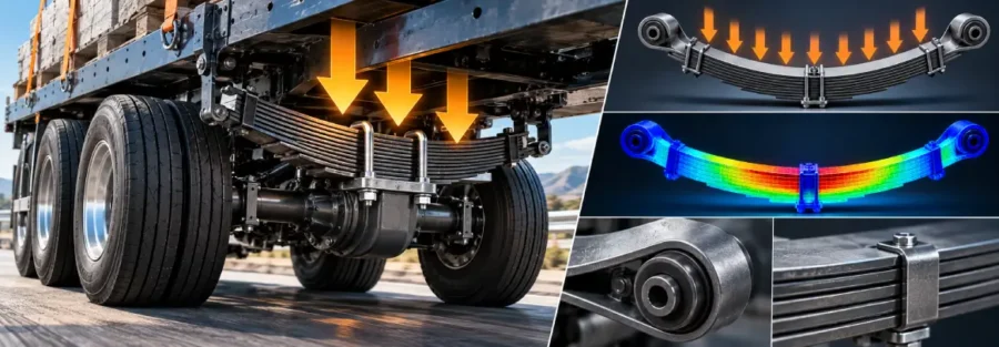
Leaf springs remain widely used in commercial vehicles because they can carry substantial loads while also contributing to axle location, ride control, and longitudinal force management. But determining whether a leaf spring is adequately designed involves much more than checking the vehicle’s rated axle weight.
A proper leaf spring design must account for static axle loading, payload distribution, suspension geometry, dynamic road loads, spring deflection, stress levels, and fatigue life. For commercial vehicles that operate over demanding roads and carry variable payloads, the difference between a nominal load calculation and a realistic durability assessment can be significant.
Engineering studies of commercial-vehicle leaf springs commonly combine analytical calculations, finite element analysis, multibody simulation, road-load data, and physical testing to establish stiffness, stress, and durability. SAE technical work has also demonstrated the value of correlating CAE results with rig and road testing before finalizing a leaf spring design.
What Determines Leaf Spring Load Capacity?
The load capacity of a leaf spring depends on several design and operating parameters rather than one number.
Important factors include:
- Maximum axle load
- Number and arrangement of leaves
- Leaf thickness and width
- Effective spring length
- Material properties
- Spring curvature
- Shackle and eye geometry
- Suspension mounting arrangement
- Static spring deflection
- Dynamic load amplification
- Braking and driving loads
- Lateral and wind-up loads
- Fatigue requirements
For a commercial vehicle, the first step is to establish the load that each spring actually carries. Using the gross vehicle weight alone can produce an incorrect result because axle loading is affected by payload distribution, wheelbase, center of gravity, and suspension architecture.
Step 1: Determine the Design Axle Load
Start with the maximum operating condition of the vehicle.
If the rear axle group carries a total vertical load (W_a), and the suspension has two springs supporting the axle, a simplified first estimate for the static load per spring is:
Spring load = Axle load / Number of supporting springs
For example, if a single rear axle carries 10,000 kg under a particular loading condition:
Axle load = 10,000 × 9.81 = 98,100 N
With two equally loaded leaf springs:
Static spring load ≈ 49,050 N per spring
This is only a starting point. Real suspension systems may not distribute the load perfectly equally. Tandem axles, equalizers, asymmetric payloads, road inputs, and suspension geometry can significantly change the force carried by individual springs.
For this reason, the static axle calculation should be followed by a vehicle-level load assessment when the design is being developed for production.
Step 2: Account for Dynamic Loading
A commercial vehicle does not operate under static loading conditions.
When the vehicle travels over bumps, potholes, rough roads, or uneven surfaces, the vertical forces transmitted through the suspension can exceed the static axle load. Braking, acceleration, cornering, and axle wind-up can introduce additional loading conditions.
A preliminary design calculation may use a dynamic load factor:
Dynamic spring load = Static spring load × Dynamic load factor
For example, if the calculated static spring load is 49,050 N and a preliminary design factor of 1.5 is selected:
Dynamic design load = 49,050 × 1.5 = 73,575 N
The appropriate factor should not simply be selected from a generic rule of thumb for a final design. It should reflect the intended vehicle, road conditions, duty cycle, suspension configuration, and available test or road-load information.
For durability development, measured road-load data provides a more representative basis for determining the actual load spectrum. Recent SAE work on commercial-vehicle leaf springs describes the use of road-load data with FEA for virtual validation, while other studies have used multibody simulation to generate durability loads.
Step 3: Calculate Spring Deflection and Stiffness
Spring rate is another fundamental design parameter.
The spring rate can be expressed as:
Spring rate = Change in load / Change in deflection
A spring that is too stiff can adversely affect ride comfort and increase loads transferred into the chassis and other suspension components. A spring that is too soft may allow excessive suspension travel, poor ride height control, or undesirable axle movement.
Leaf geometry has a direct influence on stiffness. Thickness, width, effective length, number of leaves, and material properties all affect the load-deflection relationship.
For a production design, engineers should establish the complete load-deflection curve rather than relying only on one calculated stiffness value.
FEA can then be used to evaluate whether the nonlinear behavior of the leaf assembly, including contact between leaves where relevant, is consistent with the intended design.
Step 4: Check Bending Stress
Once the design loads are established, the next question is whether the leaf spring can withstand them without exceeding the allowable stress for the selected material and manufacturing condition.
A simplified beam-based calculation can provide an initial estimate of bending stress:
σ = M / Z
where:
- σ = bending stress
- M = bending moment
- Z = section modulus
For a rectangular leaf section, the section modulus depends strongly on its width and thickness. Because stress is highly sensitive to thickness, relatively small changes in leaf thickness can have a substantial effect on structural performance.
However, a real leaf spring is not simply an isolated rectangular beam. Spring eyes, clamps, interleaf contact, mounting conditions, curvature, friction, and local geometry can produce stress distributions that are not captured adequately by a simple hand calculation.
This is where detailed finite element analysis becomes important.
Step 5: Evaluate the Complete Leaf Spring Assembly
A useful FEA model should represent the actual design closely enough to reproduce its structural behavior.
Depending on the engineering objective, the analysis may include:
- Nonlinear material behavior where required
- Contact between individual leaves
- Friction between leaves
- Spring-eye constraints
- Shackle movement
- U-bolt or clamp loads
- Axle attachment
- Large deformation
- Multiple operating load cases
U-bolt clamping force can also influence fatigue behavior. SAE research specifically examining commercial-vehicle leaf springs found that U-bolt fixing force needs to be considered when evaluating fatigue strength.
This is one reason why simply applying an axle load to an isolated spring model may not provide a sufficiently realistic durability assessment.
Step 6: Perform Fatigue Validation
Passing a static stress check does not automatically mean that a leaf spring will achieve the required service life.
Commercial-vehicle leaf springs experience repeated loading throughout their operating life. Fatigue assessment therefore needs to consider the stress range and number of cycles associated with the vehicle’s duty cycle.
A typical durability workflow involves:
- Generate or measure representative load histories.
- Determine critical stress locations using FEA.
- Convert the stress history into fatigue cycles.
- Apply an appropriate S-N or strain-life approach.
- Account for mean stress where applicable.
- Calculate cumulative fatigue damage.
- Compare predicted life with the required service life.
- Correlate the results with component or vehicle testing.
Rainflow cycle counting and Palmgren-Miner damage accumulation are among the established methods used in commercial-vehicle durability studies. SAE research has applied this approach to leaf spring durability using road and proving-ground data.
Why Vehicle-Level Simulation Matters
One of the most important aspects of leaf spring design is understanding that the spring does not operate independently.
The forces acting on it depend on the vehicle’s:
- Mass distribution
- Suspension geometry
- Tire characteristics
- Payload
- Braking conditions
- Road profile
- Axle configuration
- Vehicle speed
Multibody dynamics can be used to calculate suspension forces and moments under different maneuvers and road conditions. These loads can then be transferred into a detailed FEA model for stress and fatigue assessment.
This MBD-to-FEA workflow has been used in commercial-vehicle leaf spring development to obtain internal forces and moments for subsequent structural and fatigue calculations.
It also provides a better route for design optimization because engineers can evaluate the spring against realistic operating conditions instead of optimizing it around a single static load case.
Common Leaf Spring Design Mistakes
Several issues can lead to inaccurate load-capacity or durability predictions:
- Designing only against the nominal axle rating
- Ignoring payload distribution
- Applying an arbitrary dynamic factor
- Using unrealistic FEA boundary conditions
- Neglecting leaf-to-leaf contact
- Ignoring U-bolt clamping effects
- Checking maximum stress without fatigue analysis
- Using a generic fatigue load instead of a representative duty cycle
- Validating the spring without correlating simulation against test data
A robust design process should progressively increase model fidelity as the project moves from concept development to final validation.
How Caliber Technologies Can Support Leaf Spring Development
Leaf spring development often requires more than a single FEA analysis. The most useful engineering workflow connects vehicle behavior with component-level structural performance.
Caliber Technologies can apply a simulation-led process covering:
- Suspension and vehicle-level multibody dynamics
- Leaf spring load extraction
- Static and nonlinear FEA
- Stress and deformation analysis
- Fatigue and durability assessment
- Load-case development
- Design optimization
- Simulation-to-test correlation
The objective is not simply to determine whether a spring survives one load case. It is to understand how the complete suspension behaves, identify the critical operating conditions, and use that information to develop a design with the required strength, stiffness, durability, and weight characteristics.
Conclusion
Calculating leaf spring load capacity for a commercial vehicle is best treated as a complete engineering process rather than a single load-versus-strength calculation. Static axle loading provides the starting point, but dynamic suspension forces, spring stiffness, local stress, fatigue loading, and real operating conditions determine whether the final design will perform reliably.
A combination of vehicle dynamics, multibody simulation, FEA, fatigue analysis, and physical correlation allows engineers to move from basic axle loads to a more realistic prediction of structural performance and service life. Research and industry studies have demonstrated this progression from analytical calculations to simulation, road-load assessment, rig testing, and final correlation.
For commercial-vehicle manufacturers and component suppliers developing or validating a leaf spring, this approach can reduce design iterations while providing a stronger technical basis for durability decisions.
Frequently Asked Questions
How do you calculate the load capacity of a leaf spring?
Start by determining the load carried by the axle and distributing it across the supporting springs. The calculation should then account for dynamic loading, suspension geometry, spring stiffness, material strength, and the required safety and durability conditions. For production development, FEA and vehicle-level simulation provide a more complete assessment than a static calculation alone.
What is the maximum load a leaf spring can carry?
There is no universal maximum load for a leaf spring. Its capacity depends on geometry, material, number of leaves, thickness, effective length, mounting arrangement, allowable stress, deflection requirements, and operating conditions. The vehicle’s axle load rating should therefore not be treated as the spring’s independent capacity.
How is leaf spring fatigue life calculated?
Fatigue life is generally calculated from the stress history generated by the expected operating loads. Engineers identify critical stresses using FEA, perform cycle counting on the load or stress history, and use appropriate fatigue data to estimate cumulative damage and service life. Commercial-vehicle studies commonly correlate these calculations with rig or road testing.
Can FEA predict leaf spring fatigue life?
Yes. FEA can provide the stress and strain information needed for fatigue assessment. The accuracy of the prediction depends on the quality of the geometry, material data, boundary conditions, contact assumptions, loading history, and fatigue properties. Physical correlation remains important for validating the model.
Why is multibody dynamics used for leaf spring design?
Multibody dynamics helps determine the forces and moments generated by the complete vehicle or suspension system during maneuvers and road inputs. These time-dependent loads can then be used in component-level FEA and fatigue analysis.
What information is required for leaf spring analysis?
Typical inputs include vehicle and axle weights, payload distribution, spring geometry, material properties, suspension hard points, tire and wheel information, operating conditions, road-load data where available, and the required durability target.