Electric motor performance cannot always be evaluated from electromagnetic performance alone. Torque, efficiency, flux density, and back EMF may meet the design requirements while localized losses create excessive temperatures in windings, cores, magnets, or other components.
This makes electromagnetic and thermal analysis of electric motors a connected multiphysics problem. Electromagnetic analysis determines where losses occur, while thermal analysis determines how those losses become heat, where hot spots develop, and whether the motor can operate within its thermal limits.
Why Electromagnetic and Thermal Analysis Must Work Together
Copper, iron, rotor, and other electromagnetic losses ultimately become heat. At the same time, temperature changes winding resistance and can affect magnetic material behaviour. A rise in winding temperature, for example, increases resistance and can increase copper losses further.
Analysing these effects together provides a more realistic understanding of motor efficiency, temperature rise, cooling requirements, and operating capability. This is particularly important for high-power-density motors and applications involving variable speed, overload, acceleration, or continuous duty.
2D and 3D Electromagnetic Motor Modeling
2D electromagnetic FEA provides an efficient method for evaluating flux density, saturation, torque, back EMF, current density, torque ripple, and electromagnetic losses across the active motor section. It is well suited to design iterations and parameter studies.
3D electromagnetic analysis becomes important when axial effects, end windings, rotor skew, axial leakage, complex rotor geometry, or localized eddy currents influence performance. The modelling approach should therefore match the physical features that affect the engineering result.
Electromagnetic Losses and Heat Generation
The electromagnetic model provides the loss data required for thermal analysis. Copper losses depend on winding current and resistance, while AC effects can become important at higher frequencies. Iron or core losses are associated with hysteresis and eddy-current effects and depend on flux density, frequency, and electrical steel properties.
Rotor, permanent-magnet, and harmonic losses may also contribute to the thermal load. For accurate thermal prediction, the important output is not simply total motor loss but its spatial distribution.
Mapping Electromagnetic Losses into the Thermal Model
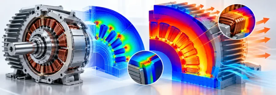
Spatially resolved electromagnetic losses can be transferred directly into the thermal model as heat sources. Winding losses are applied to winding regions, core losses to the relevant magnetic components, and other losses to their corresponding locations.
This approach preserves the relationship between electromagnetic behaviour and thermal loading. Using only average losses can conceal localized heating and underpredict critical hot spots.
The thermal model then evaluates heat conduction through the motor and heat rejection through the available cooling paths.
Winding Temperature, Hot Spots and Cooling
Winding temperature is a critical motor-design output because excessive temperature can accelerate insulation ageing and reduce service life. Thermal analysis can also identify hot spots in the stator, rotor, magnets, housing, or other components.
Accurate prediction requires realistic thermal resistance paths and cooling boundary conditions. These can include conduction through insulation and laminations, housing heat transfer, coolant temperature, convection, contact resistance, air flow, or liquid cooling conditions.
Thermal FEA can evaluate temperature distribution and heat paths, while CFD can be used where coolant flow, pressure drop, or convective heat transfer requires detailed analysis.
Coupled Electromagnetic-Thermal Simulation
A coupled workflow starts with electromagnetic analysis to calculate field behaviour and spatially distributed losses. These losses are transferred to the thermal model to calculate temperature distribution and identify limiting components.
The calculated temperatures can then be fed back into the electromagnetic model because resistance and magnetic properties are temperature dependent. For variable operating conditions, transient coupled simulation can evaluate temperature response across a complete duty cycle.
This provides a stronger representation of actual motor behaviour than analysing electromagnetic and thermal performance independently.
Engineering Outputs and Design Decisions
The value of the analysis lies in the engineering decisions supported by the results.
Electromagnetic simulation provides flux density, current density, torque, back EMF, efficiency, saturation, and loss distribution. Thermal simulation provides winding temperature, hot-spot temperature, component temperatures, thermal gradients, heat-flow paths, and temperature rise.
These outputs identify what limits the motor and why. Excessive winding temperature may require changes to conductor sizing, winding configuration, current limits, or cooling capacity. High core losses may lead to changes in electrical steel, lamination design, or magnetic geometry. High magnet temperature may require changes to magnet material, rotor design, cooling, or the operating envelope.
The workflow therefore moves from electromagnetic losses to thermal response, component limits, design modification, and validation.
Caliber Technologies: Multiphysics Product Engineering
Caliber Technologies applies electromagnetic and thermal simulation as an integrated multiphysics product engineering workflow. Electromagnetic FEA can establish field behaviour and spatially resolved heat sources, which can then be transferred into thermal models to evaluate temperature distribution, hot spots, thermal resistance paths, and cooling performance.
This approach helps engineering teams make informed decisions on motor geometry, materials, winding configuration, cooling architecture, operating limits, and product validation.
Rather than treating electromagnetic and thermal analysis as separate FEA tasks, the workflow connects loss generation, heat transfer, temperature response, and motor operating capability within the product-development process.
Need support with electric motor design or simulation? Email operations@thecalibertech.com to discuss your engineering requirements.
Conclusion
Electromagnetic and thermal analysis of electric motors provides a connected view of performance, losses, temperature, and operating limits. Electromagnetic FEA determines where losses originate, while thermal analysis establishes how those losses affect component temperatures and cooling requirements.
By combining 2D or 3D electromagnetic modelling, spatial loss mapping, thermal analysis, and realistic cooling conditions, engineers can identify thermal constraints and make targeted design changes before physical validation.
Caliber Technologies supports this multiphysics engineering approach to help evaluate motor performance, thermal behaviour, cooling strategies, and design limitations.