Why Steering Knuckle Structural Analysis Matters
A steering knuckle connects key front-wheel components, including the wheel hub, suspension links, and steering system. It transfers forces between the tire and suspension while supporting steering movement and wheel alignment.
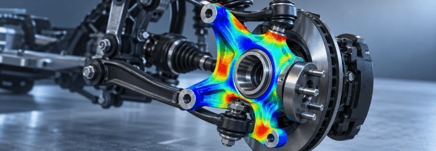
During vehicle operation, the component experiences loads from braking, cornering, road impacts, and changes in wheel loading. These forces can combine to create high local stresses around bearing seats, mounting holes, link attachment points, and changes in component thickness.
Steering knuckle FEA helps engineers understand how these loads affect structural strength and deformation before committing to physical prototypes or production tooling.
Key Engineering Challenges in Steering Knuckle Design
1. Stress Concentration Around Mounting Features
Bolt holes, bearing seats, and suspension attachment points can create local stress concentrations. Poorly managed stress levels may contribute to yielding, fatigue cracking, or premature component failure.
Finite element analysis helps identify these regions and assess whether changes to fillet radii, wall thickness, or local geometry are worth evaluating.
2. Combined Braking and Cornering Loads
A steering knuckle does not experience just one isolated load during normal driving. Braking forces, lateral cornering forces, and vertical road loads can act together.
A realistic analysis should consider relevant combinations of these forces, with load directions and magnitudes based on the vehicle’s intended use and engineering requirements.
3. Deformation and Wheel Alignment
Excessive deformation can affect suspension geometry, steering response, and wheel alignment under load. Engineers can use FEA to evaluate displacement and stiffness at critical interfaces, not just peak stress.
4. Fatigue Under Repeated Loading
Repeated load cycles can initiate fatigue damage, particularly around geometric transitions and highly stressed attachment regions. A static stress result alone cannot establish fatigue life.
Fatigue assessment requires appropriate cyclic load histories, material fatigue properties, and consideration of surface condition and manufacturing details.
How Steering Knuckle FEA Is Performed
1. CAD preparation and geometry review
Review the component geometry, material specification, interfaces, and relevant design features. Remove only details that do not materially affect the analysis.
2. Mesh generation
Create a suitable finite element mesh, refining it around fillets, holes, bearing seats, and attachment regions where stress gradients may be high. Check mesh sensitivity before relying on peak results.
3. Boundary conditions and load cases
Represent hub, bearing, and suspension interfaces appropriately. Apply relevant braking, cornering, vertical, and other design loads without unnecessarily over-constraining the component.
4. Structural results and validation
Review stress, displacement, load paths, and critical regions. Check equilibrium, reaction forces, contact behaviour where applicable, and mesh convergence before drawing design conclusions.
What Engineers Evaluate in the Results
A useful steering knuckle FEA study goes beyond generating a stress contour. The results should answer specific design questions.
| Analysis output | Engineering purpose |
|---|---|
| Von Mises stress | Identify regions requiring yield-strength assessment |
| Total and directional deformation | Check stiffness and interface displacement |
| Contact pressure | Assess relevant bearing or component interfaces |
| Fatigue assessment | Evaluate damage under repeated loading |
| Load path and reaction forces | Confirm that forces transfer through the intended structure |
| Design comparison | Assess the effect of geometry or material changes |
Results should be interpreted against the specified material properties, load cases, safety criteria, and applicable validation requirements. A visually high stress value does not automatically indicate failure; its location, physical significance, and convergence must be reviewed.
Optimising Steering Knuckle Design Using FEA
When analysis identifies a critical region, engineers can evaluate targeted design changes such as:
- Increasing local stiffness where deformation exceeds design limits.
- Refining fillets and transitions to reduce unnecessary stress concentration.
- Adjusting wall thickness or rib geometry to balance strength and mass.
- Reviewing attachment geometry and load distribution.
- Comparing alternative materials or manufacturing approaches where appropriate.
Each revised design should be reanalysed under the same relevant load cases. Weight reduction should not come at the expense of strength, fatigue performance, manufacturability, or required stiffness.
When Should Manufacturers Consider Steering Knuckle FEA?
Steering knuckle FEA can support engineering teams during:
- New steering knuckle development.
- Design changes intended to reduce component weight.
- Investigation of high-stress regions or suspected fatigue issues.
- Evaluation of alternative materials and geometries.
- Structural verification before physical testing.
- Design iteration when prototype changes are expensive or time-consuming.
FEA supports design decisions but does not automatically replace physical testing or formal validation where these are required.
Steering Knuckle FEA Services from Caliber Technologies
Caliber Technologies supports engineering analysis for automotive components, helping teams assess structural behaviour, identify critical stress regions, and evaluate design alternatives through simulation.
For steering knuckle projects, the scope can be defined around the component geometry, available material data, design load cases, interface requirements, and the engineering questions that need to be resolved.
If your team is developing or modifying a steering knuckle, contact operations@thecalibertech.com to discuss your structural analysis requirements.