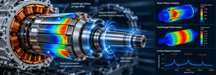
Higher motor speed is one way to increase electric powertrain power density without significantly increasing motor size. But increasing RPM also changes the mechanical loads acting on the rotor.
For high-speed permanent magnet motors, rotor bridges, magnet retention features, shafts and laminations must withstand centrifugal forces, thermal expansion and repeated speed cycles. A design that performs adequately at normal speed can develop a failure risk when pushed toward its maximum or overspeed condition.
A Typical Rotor Failure Scenario
Consider a representative permanent-magnet traction motor designed for high-speed operation. Electromagnetic analysis meets the required torque and power targets, while the initial structural analysis shows acceptable stress at the normal operating speed.
During high-speed validation, the rotor reaches an overspeed condition. Analysis identifies a high-stress concentration around the rotor bridge supporting a permanent magnet. Repeated acceleration cycles expose the same area to cyclic loading.
If the bridge does not have sufficient fatigue margin, a crack can initiate at the stress concentration and grow with repeated operating cycles.
The potential failure outcome is specific: the rotor bridge can fracture, allowing the magnet to move inside its pocket. This can create rotor imbalance, increase vibration and reduce the rotor-stator air-gap margin. In a severe case, rotor deformation or magnet displacement can lead to rotor-to-stator contact and motor failure.
This illustrates why high-speed rotor assessment needs to consider more than maximum stress at a single operating point.
Where High-Speed Rotor Stress Concentrates
Centrifugal loading increases with rotational speed, but the resulting stress is strongly influenced by rotor geometry.
Areas that commonly require detailed assessment include:
- Rotor bridges
- Magnet pockets
- Retaining sleeves
- Shaft interfaces
- Keyways and splines
- Sharp geometric transitions
A high-speed electric motor rotor stress analysis should examine both global rotor behaviour and local stress concentrations.
Reducing a peak stress may require changes to bridge geometry, fillet radii, material selection, retention method or the overall rotor architecture. Any structural change also needs to be checked against electromagnetic requirements.
Magnet Retention Becomes a Mechanical Design Constraint
Permanent magnets experience centrifugal loading during operation. At high RPM, the retention system must prevent magnet movement without creating unacceptable mechanical or electromagnetic compromises.
Depending on the rotor architecture, retention may involve:
- Rotor bridges
- Retaining sleeves
- Interference fits
- Adhesive bonding
- Combined retention methods
A thicker bridge may improve mechanical strength but affect the magnetic circuit. A lighter retention structure can support weight reduction but reduce structural margin.
For this reason, EV motor rotor design requires mechanical, electromagnetic and manufacturing considerations to be evaluated together.
Rotor Deformation and Air-Gap Stability
Structural strength is only part of the assessment. High-speed rotation can cause rotor deformation, which may affect the rotor-stator air gap.
Changes in rotor geometry can influence:
- Minimum air-gap clearance
- Magnetic performance
- Rotor balance
- Bearing loading
- Dynamic response
The objective is therefore not simply to keep stress below an allowable limit. The rotor must also maintain its required geometry throughout the operating envelope.
Overspeed and Fatigue Require Different Assessments
Maximum continuous speed and overspeed are separate load cases.
An overspeed assessment determines whether the rotor can withstand a higher rotational speed without permanent deformation, retention failure or loss of structural integrity.
Fatigue addresses a different problem. Traction motors repeatedly accelerate and decelerate, exposing components to cyclic loading. A rotor bridge can remain below its yield strength during individual events and still accumulate fatigue damage over its service life.
A durability assessment should therefore use representative speed and load histories, with particular attention to local stress concentrations.
Thermal Effects Can Change Rotor Loading
High-speed operation also produces thermal loads. Different materials within the rotor assembly expand at different rates, which can change contact pressure and internal stresses.
This is particularly relevant when the rotor contains:
- Permanent magnets
- Laminated rotor cores
- Shafts
- Retaining sleeves
A thermo-mechanical rotor analysis can determine whether temperature changes alter retention conditions or introduce additional stress that may not appear in a room-temperature structural assessment.
Rotor Dynamics at High RPM
At high rotational speeds, rotor dynamics becomes another design constraint.
Rotor imbalance, shaft flexibility, bearing stiffness and critical speeds can influence vibration. If the operating range approaches a critical speed, dynamic response can increase significantly.
Rotor dynamic analysis can be used to evaluate:
- Critical speeds
- Mode shapes
- Unbalance response
- Shaft behaviour
- Bearing effects
This becomes increasingly important as engineers increase RPM to achieve higher power density.
Using FEA to Identify Problems Before Testing
Physical overspeed and durability testing remain essential. FEA can, however, identify weak areas before hardware reaches the test bench.
Depending on the development stage, analysis can cover:
- Centrifugal stress
- Rotor deformation
- Magnet retention
- Overspeed conditions
- Thermal stress
- Fatigue
- Shaft and rotor interfaces
The useful output is not simply a stress contour. Engineers need to understand where the failure risk exists, what is causing it and which design change can improve the margin.
Designing a Rotor for Higher Speed
Higher RPM can deliver greater power from a smaller motor, but the mechanical design margin becomes more demanding.
High-speed rotor development requires the interaction between stress, retention, deformation, fatigue, thermal behaviour and rotor dynamics to be considered during design rather than only during final validation.
Finding a rotor bridge weakness during simulation is considerably easier to address than discovering a fractured bridge or magnet-retention problem during physical testing.
How Caliber Supports High-Speed E-Motor Development
Caliber Technologies provides engineering analysis and simulation support for electric powertrain development.
Our capabilities include:
- Rotor structural and stress analysis
- FEA-based design assessment
- Thermo-mechanical analysis
- Fatigue and durability assessment
- Rotor dynamics
- Design optimization
- Virtual validation
If your team is developing a high-speed electric motor and needs support with rotor stress, magnet retention, overspeed, fatigue or rotor dynamics, contact Caliber Technologies.