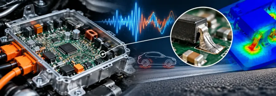
Why Thermal Cycling Causes Reliability Problems in EV Power Electronics
EV power electronics experience repeated temperature changes during normal vehicle operation. Power-up, high-load driving, regenerative braking and shutdown create thermal cycles that cause components and circuit boards to expand and contract.
Solder joints connect electronic components to printed circuit boards (PCBs). When connected materials expand at different rates, these joints experience repeated mechanical strain. Over time, the strain can initiate fatigue cracks, increase electrical resistance and eventually cause intermittent faults or complete circuit failure.
For EV power electronics manufacturers, thermal cycling analysis is important for identifying solder joint reliability risks before physical testing or field operation exposes them.
How Temperature Changes Create Solder Joint Fatigue
Solder joints sit between materials with different coefficients of thermal expansion. Silicon devices, copper conductors, PCB laminates and solder alloys do not expand or contract by the same amount when their temperatures change.
This mismatch creates cyclic strain around solder joints, particularly where components are relatively large or rigidly attached to the PCB.
Repeated temperature changes can cause:
- Fatigue crack initiation: Localised strain builds around solder joints during repeated heating and cooling.
- Crack propagation: Continued cycling extends existing cracks and reduces the effective electrical connection.
- Intermittent electrical faults: Damaged joints may lose reliable contact under certain temperatures or operating conditions.
- Reduced service life: Components can fail before reaching their intended operating lifetime.
The severity depends on the temperature range, cycle duration, material properties, component geometry and number of cycles. A design that performs well at a steady operating temperature may still develop fatigue damage under repeated thermal loading.
Which Areas of an EV Power Electronics Assembly Need Attention?
Thermal cycling does not affect every connection equally. The component layout, package size and local temperature distribution influence where strain concentrates.
- Power semiconductor packages: Large or rigidly mounted devices can create substantial expansion mismatch between the package, solder layer and PCB.
- PCB-to-component connections: Solder joints beneath surface-mounted components may experience repeated shear strain as the board and component expand differently.
- High-power connection points: Areas near power devices and current-carrying connections may experience localised temperature variations during changes in electrical load.
- PCB regions with uneven heating: Components operating at different temperatures can create local thermal gradients, causing different parts of the board to expand by different amounts.
Identifying these locations helps engineers focus analysis on the connections most likely to experience fatigue damage.
How Thermal Simulation Helps Assess Solder Joint Reliability
Thermal analysis can establish the temperature distribution across a power electronics assembly under defined operating conditions. This may include power losses, heat transfer through the enclosure, cooling performance and changes in component temperature during operation.
The resulting temperature data can be used in structural analysis to evaluate thermal expansion, deformation and stress in the PCB and connected components.
For fatigue assessment, engineers may examine local strain in solder joints and apply an appropriate fatigue or life-prediction method. Depending on the solder material and modelling approach, this can include inelastic strain or creep-fatigue effects.
A useful analysis should consider the actual thermal cycle rather than only the maximum operating temperature. The heating and cooling rates, temperature range, dwell time and expected number of cycles can all influence the predicted damage.
Simulation results depend on the accuracy of material data, boundary conditions, component representation and fatigue models. Physical thermal cycling tests remain important for validating the predicted behaviour.
Design Changes That Can Reduce Thermal Cycling Risk
When analysis identifies high strain or fatigue risk, engineers can assess design changes before committing to tooling or production hardware.
Potential improvements include:
- Reviewing component placement: Reduce exposure to severe temperature gradients where layout constraints allow.
- Evaluating solder joint geometry: Assess whether package dimensions, joint thickness or connection design contribute to local strain.
- Improving thermal management: Reduce excessive temperature swings and uneven heating through suitable cooling and heat-transfer design.
- Reviewing PCB and package materials: Assess the effect of material expansion properties on joint strain.
- Comparing design alternatives: Use simulation to evaluate whether proposed changes reduce fatigue indicators without creating other structural or thermal problems.
The aim is not simply to reduce peak temperature. A design must also manage repeated expansion and contraction over its expected operating conditions.
EV Power Electronics Thermal Cycling Analysis by Caliber Technologies
Caliber Technologies supports engineering teams with CAE simulation, structural assessment and thermal analysis for demanding engineering applications. For EV power electronics, this type of engineering assessment can help investigate temperature-driven deformation, material interaction and potential solder joint fatigue risks.
By combining thermal results with structural and fatigue assessment, engineering teams can compare design alternatives and identify areas requiring further validation.
Planning a thermal reliability assessment for an EV power electronics assembly?
Contact Caliber Technologies at operations@thecalibertech.com to discuss your engineering requirements.