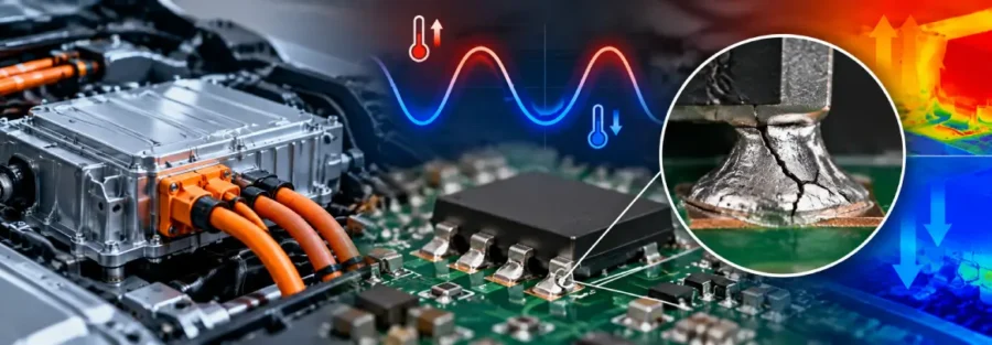
Why Onboard Charger Enclosures Face Structural Challenges
An electric vehicle onboard charger (OBC) converts incoming AC power into DC power for battery charging. Its enclosure must protect internal electronics while supporting mounting loads and withstanding vibration transmitted through the vehicle structure.
The challenge is particularly important in compact EV platforms, where the charger must fit within restricted packaging space alongside other electrical and mechanical systems. Mounting brackets, enclosure walls and attachment points must provide sufficient stiffness without adding unnecessary weight.
Problems can emerge when an enclosure designed around static loads experiences repeated road-induced vibration. Local deformation, stress concentrations around fasteners and flexible mounting brackets can contribute to fatigue damage over time.
For engineering teams developing a new charger or adapting an existing unit to a different vehicle platform, structural analysis can help identify these weaknesses before repeated physical testing.
Where Structural Weaknesses Develop
1. Stress Concentrations Around Mounting Points
Mounting holes and bolted interfaces transfer loads between the charger enclosure and the vehicle structure. These locations can experience elevated stresses when loads are concentrated around small contact areas or when the mounting arrangement allows uneven load distribution.
Local geometry also matters. Sharp transitions, thin sections and insufficient reinforcement can increase stress near attachment points.
A structural assessment should examine the enclosure and mounting interfaces under representative loading conditions. Simply increasing the thickness of the entire housing may add weight without addressing the specific source of the stress concentration.
2. Enclosure Deformation Under Dynamic Loading
Road vibration introduces time-varying loads into the vehicle structure. The resulting response depends on the enclosure’s stiffness, mass distribution, support conditions and excitation frequencies.
Flexible enclosure panels may experience greater deformation than expected under static loading. If the assembly has a natural frequency near a significant excitation frequency, the response may increase further.
Modal analysis can help identify natural frequencies and mode shapes, while dynamic analysis can estimate the response to defined vibration inputs. These results help engineers identify flexible regions and evaluate possible structural changes.
3. Mounting Bracket Fatigue
Mounting brackets can experience repeated bending and cyclic stress as the vehicle operates over different road surfaces. Even when peak stresses remain below the material’s yield strength, repeated loading may contribute to fatigue damage.
Bracket geometry, welds where present, fastener locations and material selection all influence durability.
Fatigue assessment should use a suitable representation of the expected load history. A single static stress result cannot establish the service life of a component exposed to repeated vibration.
4. Interaction Between the Enclosure and Internal Components
The enclosure does not operate in isolation. Internal electronics, circuit boards, connectors and other components contribute mass and may have their own mechanical support requirements.
Excessive housing deformation or vibration can affect how loads are transmitted to internal assemblies. The analysis must therefore reflect the relevant component masses, attachment conditions and interfaces when these factors materially influence the structural response.
The enclosure can meet its own strength requirements while the complete assembly still experiences unacceptable vibration. This is why the scope of the assessment should match the actual failure concern.
How Structural Simulation Helps Assess OBC Durability
Static Structural Analysis
Static structural analysis helps evaluate stress, deformation and load transfer under defined mounting and service loads. It can identify areas where the enclosure or brackets may require additional stiffness or improved geometry.
The model should represent realistic fastener constraints, contact interfaces, material properties and relevant load cases. Overly rigid boundary conditions can distort the predicted stress distribution and conceal weaknesses elsewhere in the assembly.
Modal and Dynamic Analysis
Modal analysis identifies the natural frequencies and corresponding deformation patterns of the enclosure assembly. These results can be compared with the expected vibration environment to identify potential resonance concerns.
Where the excitation profile is available, harmonic or random vibration analysis can help assess the dynamic response. The selected method should reflect the type of loading and the test or operating conditions being investigated.
Fatigue Assessment
Where repeated vibration is the suspected cause of damage, fatigue analysis can help estimate the risk of crack initiation in critical structural regions.
The assessment should account for the relevant stress history, material fatigue properties and failure mechanism. Welded joints, bolted connections and formed sheet-metal sections may require different modelling assumptions or assessment methods.
Predicted fatigue life should be treated as an engineering estimate, not a guarantee of field durability. Correlation with physical testing strengthens confidence in the results.
Design Changes to Consider Before Another Prototype Build
Once the critical load paths and deformation patterns are identified, engineers can assess targeted changes rather than redesigning the complete enclosure.
- Reinforce critical mounting regions: Evaluate local ribs, flanges or geometry changes where analysis identifies excessive stress or deformation.
- Improve bracket stiffness: Review bracket dimensions, support locations and load paths to reduce cyclic bending.
- Review enclosure panel behaviour: Assess whether local stiffness changes can reduce excessive deformation without creating unnecessary mass.
- Reconsider mounting interfaces: Investigate fastener arrangement, contact conditions and support stiffness where uneven load transfer contributes to the problem.
- Validate the revised design: Repeat the relevant simulation and physical testing to confirm that the changes address the original failure without creating new issues.
Any modification must also preserve electrical clearances, sealing, thermal performance, manufacturability and service access. Structural improvements should be assessed against the complete charger’s design requirements.
When Specialist Engineering Support Is Useful
An EV startup may need additional engineering support when an onboard charger enclosure repeatedly fails vibration testing, mounting brackets develop cracks, or simulation results do not explain the observed deformation.
External CAE support can help investigate the load paths, evaluate alternative enclosure designs and assess fatigue risks before another prototype iteration. The analysis is most useful when CAD geometry, material information, mounting details and available test results can be provided.
Caliber Technologies supports engineering teams with structural simulation, product design and durability assessment. For onboard charger projects, the analysis scope can be defined around the specific enclosure, mounting arrangement and validation requirements.
Discuss Your EV Engineering Requirements
If your onboard charger enclosure is experiencing excessive vibration, mounting-point stress or recurring durability issues, Caliber Technologies can discuss the available design data and determine a suitable structural analysis approach.