
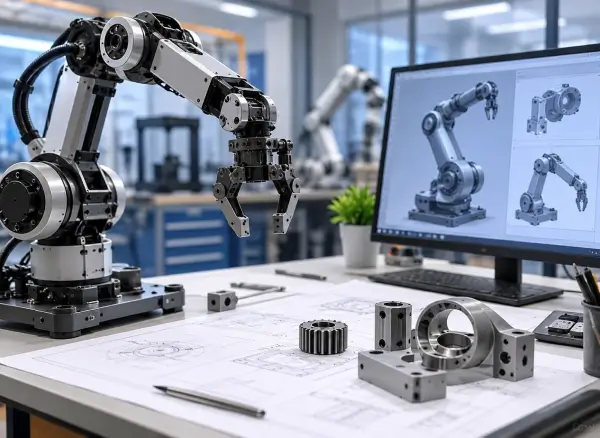
Robotics Mechanical Design Services
A robotic mechanism has to move as intended, carry its loads and maintain its structural behavior throughout its working range. The difficult part is often not creating the geometry. It is deciding where the material belongs, how the joints should be supported, how loads should travel through the assembly, and what happens when the robot accelerates, stops or operates repeatedly.
Caliber Technologies provides robotics mechanical design services for robotic arms, mechanisms, automation equipment and custom robotic products. We work on the mechanical structure behind the robot, from individual components and joints to complete assemblies, with CAD, CAE and FEA used where engineering verification is required.
Mechanical Design Starts With the Way the Robot Will Be Used
The mechanical design of a robot is closely tied to its operating conditions.
A link that looks adequate in a static CAD assembly may deflect too much when the arm reaches maximum payload. A joint housing may need additional stiffness because of the loads transferred through the bearing arrangement. A lightweight structure may meet its static strength requirement but introduce an undesirable vibration mode.
These are mechanical design decisions, not just CAD decisions.
Our robotics mechanical engineering work considers the relationship between the structure, joints, actuators, payload, movement and surrounding components before the design is finalized.
Typical design work includes:
- Robot links and structural members
- Joint housings
- Mechanical mechanisms
- Shafts and bearing supports
- Actuator interfaces
- End-effector mounts
- Structural brackets
- Frames and support structures
- Mechanical enclosures
- Custom assemblies
For projects that begin with an existing concept or CAD model, we can work from the current design rather than starting over.
Designing the Mechanical Structure Around the Load Path
One of the first questions in robotic mechanical design is simple: where does the load go?
Payload forces travel through the end effector, wrist, links, joints and supporting structure before reaching the robot base. Each interface along that path can influence stress, deformation and stiffness.
The design therefore needs to account for more than the nominal strength of an individual component.
We look at factors such as:
- Payload and tooling mass
- Robot reach
- Joint locations
- Load direction
- Bending and torsional loads
- Actuator mounting
- Bearing support
- Fastener locations
- Structural interfaces
- Component stiffness
- Overall mass
This becomes particularly important when developing robotic arms. A change in link length or cross-section can alter both the local stresses and the loads seen by other components.
Robotic Mechanism Design
Not every robotics project involves a conventional six-axis arm.
Many applications require a mechanism built around a specific movement, envelope or process. That could be a rotary mechanism, linkage, actuator-driven assembly, positioning mechanism or custom end-effector structure.
Our robotic mechanical design services can cover the mechanical development of these systems, including:
Linkages and Mechanisms
Mechanical arrangements that convert actuator movement into the required motion.
Joint Assemblies
Housings, shafts, bearing supports and interfaces designed around the expected loads and movement.
Actuator Mounting
Mechanical interfaces that transfer actuator loads into the surrounding structure without introducing unnecessary flexibility.
End-Effector Structures
Mechanical mounting and support structures for tooling, grippers and process equipment.
Supporting Structures
Frames, brackets and mounting structures that connect the robotic mechanism to the rest of the machine.
The design is developed around the actual function of the mechanism rather than fitting the application into a predefined component arrangement.
Robot Mechanical Design for Robotic Arms
Robotic arm design creates a particularly close relationship between mass, stiffness, reach and payload.
Increasing reach increases the moment generated by the payload. Increasing structural mass adds to the loads that the actuators need to move. Reducing material can lower mass but may also reduce stiffness and increase deflection.
This is where mechanical engineering decisions have a direct effect on the robot’s overall behavior.
We can work on mechanical elements such as:
- Upper and lower arm links
- Joint housings
- Wrist structures
- Actuator mounts
- Bearing supports
- Structural ribs
- End-effector interfaces
- Mounting structures
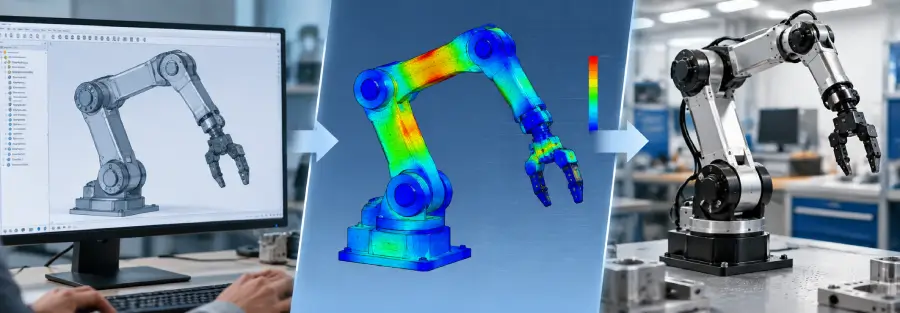
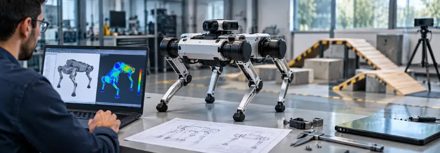
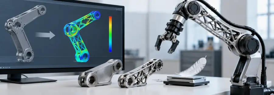
For designs where structural performance is a concern, the mechanical model can be taken into FEA for stress, deformation, stiffness, modal or fatigue assessment. Caliber’s existing robotics work uses this CAD-to-FEA connection to study robotic-arm loading and design changes before physical hardware is built.
Mechanical Design and CAD Need to Work Together
A mechanical design is only useful when it can be developed into accurate engineering geometry.
Our robotics CAD design services support the detailed development of components and assemblies after the mechanical approach has been established.
This can involve:
- Creating new components
- Building complete assemblies
- Modifying existing CAD
- Developing interfaces
- Creating detailed features
- Preparing models for FEA
- Producing engineering drawings
- Revising designs after analysis
We can work from an engineering requirement, an existing CAD assembly, a prototype, drawings or a concept.
The important part is that CAD remains connected to the engineering requirement. If an FEA result shows excessive deflection in a particular area, for example, the geometry can be revised and analyzed again rather than treating the simulation as a final report.
Designing for Stiffness, Not Just Strength
Strength and stiffness are not the same engineering problem.
A component can remain below its material strength limit and still deform enough to affect the robot’s performance.
This can matter when the robot requires:
- Accurate end-effector positioning
- Repeatable movement
- Controlled tool orientation
- Stable process loads
- High payload capability
- High-speed motion
For these applications, mechanical design may need to focus on section geometry, support locations, load paths and material distribution rather than simply increasing wall thickness.
Our CAE and FEA capabilities can be used to examine these decisions before committing to hardware. The results can then guide changes to the mechanical design.
Weight Reduction Has to Be Treated as a System Problem
Reducing the weight of a robotic component is not simply a matter of removing material.
A lighter link can reduce the load on an actuator, but if stiffness drops too far, the end effector may experience greater deflection. If the mass distribution changes, dynamic behavior can also change.
For this reason, lightweighting needs to be considered alongside:
- Stress
- Deflection
- Stiffness
- Natural frequency
- Fatigue
- Actuator loading
- Manufacturing requirements
Caliber’s robotics engineering work includes structural FEA and optimization for evaluating these trade-offs in robotic hardware.
The objective is not to produce the lightest possible component. It is to develop a component that satisfies the required mechanical performance without carrying unnecessary material.
Mechanical Design for Real Manufacturing
A design can work well on screen and still be difficult to manufacture.
The manufacturing method influences wall thickness, feature size, tolerances, joining methods, access for machining and the way components are assembled.
Our mechanical design work can account for the intended manufacturing approach, including:
- CNC machining
- Fabrication
- Sheet metal
- Additive manufacturing
- Fastened assemblies
- Welded structures
For prototype hardware, the priority may be getting a functional component manufactured quickly. For production hardware, repeatability, tolerances, assembly time and inspection may become more important.
Those differences need to be reflected in the mechanical design.
Working With Existing Robotic Designs
A large part of mechanical engineering work involves improving something that already exists.
You may have a prototype that works but is heavier than necessary. An arm may show too much deflection. A joint may be experiencing higher loads than expected. A bracket may require reinforcement. Or the existing CAD may need to be adapted for a different payload or manufacturing process.
In these cases, we start with the current design and identify what needs to change.
The work may involve:
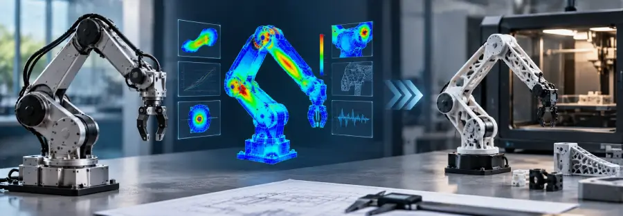
Design review → CAD modification → FEA → engineering assessment → design revision
This approach can be particularly useful when a company already has substantial development invested in a robotic product and does not want to restart the mechanical design from scratch.
Where Mechanical Design and Simulation Meet
Simulation is most useful when it influences the design.
For example, consider a robotic arm link that shows excessive deformation under maximum payload.
The engineering response might involve:
- Changing the cross-section
- Adding or relocating ribs
- Increasing section depth
- Changing material
- Modifying the joint interface
- Reducing unsupported length
- Redistributing material
The revised design can then be analyzed again.
This creates a practical connection between mechanical design and CAE, rather than treating the two as separate services.
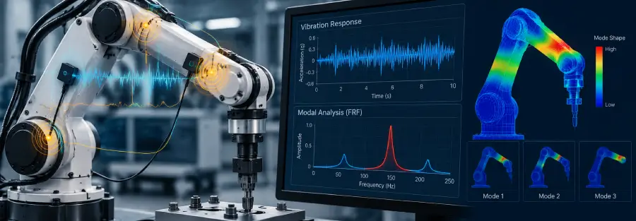
For robotics projects, this can extend into modal analysis, fatigue assessment and structural optimization when those analyses are relevant to the operating requirements. Caliber’s current robotics engineering work covers these areas as part of its broader simulation-led development approach.
What We Can Design
Our robotics mechanical engineering capabilities can be applied to a range of mechanical systems and components.
Robotic Arms
Links, joints, housings, structural members, actuator interfaces and end-effector mounting structures.
Robotic Mechanisms
Custom linkages, rotary mechanisms, positioning systems and actuator-driven assemblies.
Automation Equipment
Mechanical structures, mounts, brackets, mechanisms and supporting assemblies for automated equipment.
End Effectors
Mechanical structures and interfaces for grippers, tools and process-specific equipment.
Structural Components
Frames, brackets, supports, housings and other load-bearing components.
Custom Robotic Products
Mechanical architecture and detailed component development for companies developing their own robotic hardware.
A Practical Mechanical Engineering Workflow
The work does not need to follow a fixed sequence for every project.
For a new robotic product, the engagement may begin with mechanical architecture. For an existing design, it may begin with a CAD and structural review.
A typical development path can involve:
Requirement review
Understand the function, loads, movement, interfaces and physical constraints.
Mechanical concept
Establish the arrangement of components and the basic structural approach.
Detailed CAD
Develop the components, interfaces and assemblies.
Engineering assessment
Review loads, stiffness, movement, mass and manufacturability.
CAE / FEA
Evaluate structural behavior where analysis is required.
Design revision
Incorporate the engineering findings into the mechanical model.
Final design development
Prepare the design for prototyping, testing or manufacturing.
The actual scope depends on what your team already has and where the design currently stands.
Why Caliber Technologies for Robotics Mechanical Design?
Caliber Technologies approaches robotics mechanical design as part of the broader product engineering process.
The company works across product design, CAE simulation and structural optimization, with its robotics work extending that engineering approach to robotic arms and physical robotic hardware.
For a robotics project, this means the mechanical design can be developed with later engineering analysis in mind. Where required, CAD, structural simulation and optimization can be brought into the same development cycle.
This is useful when the requirement is not simply “create a CAD model,” but rather develop a mechanical design that needs to meet defined structural and operating requirements.
Robotics Mechanical Design Deliverables
Depending on the project, the engineering package may include:
- Mechanical concepts
- 3D CAD parts
- Robotic assemblies
- Mechanism designs
- Joint assemblies
- Structural components
- Engineering drawings
- Interface definitions
- CAD revisions
- FEA-ready models
- Structural analysis
- Design optimization studies
The deliverables are established according to the project rather than using the same package for every engagement.
Need Robotics Mechanical Design Support?
If you are developing a robotic arm, mechanism or custom robotic product and need additional mechanical engineering capacity, Caliber Technologies can support the design work around your existing development process.
Share the CAD, requirements or mechanical problem you are working on, and we can discuss the engineering scope.
Frequently Asked Questions
What is robotics mechanical design?
Robotics mechanical design is the engineering of the structures, mechanisms, joints and components that make up the physical side of a robotic system. It involves decisions around geometry, loads, movement, stiffness, materials, interfaces and manufacturing.
What is the difference between robotics mechanical design and robotics hardware design?
There is considerable overlap. Hardware design describes the physical robotic components being developed, while mechanical design focuses more deeply on how those components function as a mechanical system, including mechanisms, load paths, joints, stiffness, interfaces and manufacturability.
Can you redesign an existing robot mechanism?
Yes. Existing CAD, prototypes or mechanical assemblies can be reviewed and modified when the design needs improved stiffness, lower weight, different loading capacity, better manufacturability or other mechanical changes.
Can you design mechanical components for robotic arms?
Yes. This can include links, joint housings, actuator mounts, bearing supports, structural members and end-effector interfaces. The design can be developed around payload, reach, loading, stiffness and mass requirements.
When should FEA be used during mechanical design?
FEA is most useful when it can influence a design decision. It can be introduced during preliminary design to compare concepts or later to verify a detailed design against defined loading and performance requirements.
Can you optimize a robotic structure for lower weight?
Yes. Structural analysis can identify areas where material can potentially be removed or redistributed while maintaining required strength, stiffness and other constraints. Caliber’s robotics work includes this type of structural optimization.
Can you work with our existing CAD system and design data?
Yes. Existing CAD and engineering information can be used as the starting point for redesign, detailed development, analysis preparation or design optimization.
Can you support the mechanical design through prototyping?
Yes. The mechanical design can be developed with the intended prototype or manufacturing method in mind, with analysis and design refinement performed before the hardware moves to the next stage.
How We Provide Services
Project Scope Based Services
Time Based Projects
On-site Resource Assignment
Strategic Consulting Services
We are very glad to get client review.
Have a question? Send us a message, and we’ll respond shortly.
Tackle your toughest technical challenges in automotive engineering and reach your product development goals by leveraging the expertise of our trusted engineers.