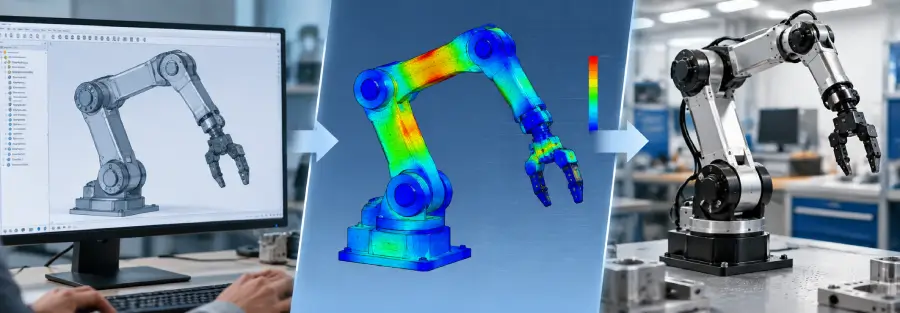
A robotic hardware design can look complete in CAD and still be far from ready for manufacturing.
The geometry may fit together. The joints may move through the required range. The assembly may look structurally substantial.
But CAD alone does not tell an engineering team whether the arm will withstand its payload, how much it will deflect, where stress will concentrate, whether a bracket will survive repeated loading, or whether a lightweight structure will develop an unfavorable vibration mode.
That is where the transition from CAD to FEA becomes important.
For robotics hardware, the objective is not simply to export a CAD file into an FEA package and generate a stress contour.
A useful CAD-to-FEA workflow connects the mechanical design to realistic loads, boundary conditions, material properties, structural requirements and design decisions.
The simulation then feeds information back into the CAD model.
CAD defines the design. FEA evaluates the design. Engineering iteration improves the design.
For robotics companies developing physical products, this workflow can reduce uncertainty before prototypes are manufactured and help engineering teams make better decisions about stiffness, strength, weight, joints and manufacturability.
What does CAD to FEA mean for robotics?
CAD to FEA is the process of taking a computer-aided design model and preparing it for finite element analysis.
For a robotic arm, the workflow typically involves:
- Creating or receiving the CAD assembly
- Reviewing the geometry for analysis
- Simplifying unnecessary features
- Defining materials and mass properties
- Representing joints and connections
- Defining loads and boundary conditions
- Creating the finite element mesh
- Running structural analysis
- Reviewing stress and deformation
- Comparing results with design requirements
- Modifying the CAD design
- Re-running the analysis
The process may then continue into:
- Modal analysis
- Vibration analysis
- Fatigue analysis
- Thermal analysis
- Optimization
- Design validation
- Prototype correlation
The important point is that CAD and FEA should not be treated as completely separate engineering activities.
The simulation should influence the design.
Why robotics hardware needs a CAD-to-CAE workflow
Robotic mechanisms are subjected to loads that change with position, payload, acceleration and operating conditions.
A robot arm may experience different structural demands when:
- The arm is fully extended
- The payload is at maximum reach
- The end effector is offset from the wrist
- Multiple axes accelerate simultaneously
- The arm decelerates rapidly
- A heavy tool is installed
- The robot operates repeatedly through the same cycle
A CAD model can represent the geometry.
It cannot, by itself, determine how that geometry behaves under these conditions.
FEA provides a way to evaluate the mechanical design before physical hardware exists.
Research on robotic-arm development has used CAD models as the starting point for FEA under different loading conditions, with the analysis then informing material and design decisions.
That is the real value of the workflow.
The CAD model is not automatically ready for FEA
One of the most common misconceptions is that an engineering CAD assembly can simply be imported into an FEA solver and analyzed.
In practice, CAD models often contain features that are useful for manufacturing but unnecessary for structural simulation.
Examples include:
- Small fillets
- Cosmetic chamfers
- Threads
- Small holes
- Logos
- Fastener details
- Tiny gaps
- Imported surface defects
- Hardware that has little structural influence
Keeping every CAD feature can make the model unnecessarily large and complicate meshing.
But excessive simplification can also be a problem.
A feature that looks small may have a significant effect on:
- Stress concentration
- Local stiffness
- Contact behavior
- Load transfer
- Natural frequency
The objective is therefore not to make the CAD model as simple as possible.
The objective is to create an analysis model that preserves the structural behavior relevant to the engineering question.
Step 1: Understand what the robotic hardware needs to achieve
Before modifying the CAD model, define the engineering requirements.
For a robotic arm, these may include:
- Payload
- Reach
- Operating speed
- Acceleration
- End-effector mass
- Positioning accuracy
- Repeatability
- Operating life
- Environmental conditions
- Mounting configuration
- External process loads
These requirements determine what needs to be analyzed.
For example, if the primary requirement is structural strength, static FEA may be the starting point.
If end-effector positioning is critical, deformation and stiffness become more important.
If the robot operates at high speed, modal and vibration analysis may be required.
If the robot performs millions of cycles, fatigue becomes important.
The analysis should therefore start with the engineering requirement, not the software.
Step 2: Review the CAD assembly
The first CAD review should identify the components that actually carry load.
For a robotic arm, this could include:
- Base
- Shoulder housing
- Upper arm
- Forearm
- Wrist
- Joint brackets
- Shafts
- Bearings
- Actuator mounts
- End-effector interface
Not every purchased component needs to be modeled with full geometric detail.
For example, a motor may be represented by its mass and mounting interface when the internal motor geometry is not relevant to the structural question.
Likewise, a gearbox can sometimes be represented through appropriate mass and connection characteristics rather than detailed internal teeth.
This approach can significantly simplify the simulation model while retaining the behavior that matters.
Step 3: Simplify the geometry without changing the engineering problem
Geometry simplification is one of the most important parts of the CAD-to-FEA process.
The wrong approach is:
Remove as much detail as possible.
The better approach is:
Remove detail that does not materially affect the result.
A small cosmetic chamfer is usually irrelevant to a global stiffness calculation.
A fillet at a highly loaded bracket may not be.
A tiny mounting hole may be irrelevant to a first-pass global analysis.
A bolt interface between two structural components may be critical.
This distinction requires engineering judgment.
For robotics hardware, common simplifications can include:
- Removing cosmetic features
- Suppressing small fillets where appropriate
- Removing threads
- Simplifying fasteners
- Replacing complex actuator geometry with equivalent masses
- Simplifying internal components
- Removing non-structural covers
The simplified model should still represent the real load path.
Step 4: Define materials correctly
Material properties are fundamental to FEA.
For structural analysis, the model may require:
- Young’s modulus
- Poisson’s ratio
- Density
- Yield strength
- Ultimate strength
- Thermal properties where relevant
- Fatigue data for fatigue analysis
For robotics hardware, material selection can also affect the dynamic response.
Two materials with similar strength may have different stiffness-to-weight characteristics.
This matters for lightweight robotic arms where both structural mass and stiffness influence actuator requirements and dynamic behavior.
Material properties should come from appropriate engineering data rather than arbitrary values.
If the material specification is still under consideration, multiple material cases can be analyzed.
That allows the engineering team to compare the structural consequences before committing to a material.
Step 5: Define joints and connections
This is where robotic hardware becomes more complicated than a simple static component.
A robot is an assembly of connected bodies.
The behavior of those connections can strongly influence the result.
Depending on the application, the model may need to account for:
- Bolted joints
- Bearings
- Shafts
- Gearboxes
- Actuator interfaces
- Welds
- Press fits
- Contact surfaces
- Joint stiffness
Assuming everything is perfectly rigid may make the model easier to solve.
It can also make the predicted structure unrealistically stiff.
For early design screening, simplified connections can be appropriate.
For detailed validation, critical interfaces may require a more representative model.
Step 6: Establish realistic boundary conditions
Boundary conditions tell the solver how the structure is supported.
They also have a major influence on the result.
Consider a robotic arm mounted to:
- A rigid laboratory base
- A steel machine frame
- A mobile robot
- A vehicle
- A flexible pedestal
These are not dynamically identical systems.
For static analysis, an incorrect constraint can alter the load path and produce misleading stress or deformation results.
For modal analysis, the effect can be even more significant because the mounting condition influences the natural frequencies and mode shapes.
The boundary condition should therefore represent the actual physical installation as closely as practical.
Step 7: Define the actual robotic load cases
A robotic arm should not normally be validated using only one load case.
Potential cases include:
Maximum payload
The arm carries its rated payload under the required operating configuration.
Maximum reach
The payload is positioned at a configuration producing a large moment about one or more joints.
Acceleration
The arm accelerates rapidly, producing additional inertial loading.
Deceleration
The robot stops or reverses direction, creating another potentially critical dynamic condition.
Offset payload
The center of gravity of the end effector or payload is displaced from the joint axis.
External process load
The robot may experience an external force from:
- Machining
- Welding
- Cutting
- Assembly
- Contact
- Material handling
Combined load case
Several loads may occur simultaneously.
The important point is to derive these cases from the actual operating envelope.
Step 8: Mesh the robotic hardware model
The CAD model has now been converted into an analysis-ready representation.
The next step is meshing.
The geometry is divided into finite elements that allow the solver to approximate the structural response.
Mesh decisions can affect:
- Accuracy
- Computational cost
- Stress resolution
- Deformation prediction
- Modal results
A very coarse mesh may miss important local behavior.
A very fine mesh everywhere may make the model unnecessarily expensive.
The useful approach is to refine the mesh where the engineering problem requires it.
Areas that may require particular attention include:
- Thin sections
- Joint interfaces
- Mounting brackets
- Sharp geometry transitions
- Load application regions
- Contact regions
- Stress concentration areas
Step 9: Perform baseline structural FEA
The first simulation should establish the behavior of the existing design.
Typical outputs include:
- Stress
- Strain
- Total deformation
- Reaction forces
- Contact pressure
- Safety margin
The results should then be compared with actual engineering requirements.
For example:
If the maximum allowable end-effector displacement is 0.5 mm, the question is not simply whether the deformation plot looks acceptable.
The question is:
Does the predicted deformation remain within 0.5 mm for the required load case and robot configuration?
That makes the simulation actionable.
Step 10: Identify the real design problem
FEA is most useful when it identifies something that can be changed.
Suppose the results show excessive deformation at the end effector.
The next question is:
Why?
Potential causes could include:
- Long unsupported link
- Insufficient section stiffness
- Flexible bracket
- Joint compliance
- Poor load path
- Excessive mass at the end effector
- Inappropriate material
- Weak mounting structure
The contour plot is not the conclusion.
It is evidence used to find the design problem.
CAD-to-FEA iteration is where the value appears
The strongest workflow is iterative.
CAD
↓
FEA
↓
Engineering interpretation
↓
Design modification
↓
FEA
↓
Design decision
This can be repeated until the design meets the relevant requirements.
A robotic-arm study integrating parametric CAD and FEA similarly describes using analysis results to evaluate alternative geometries and identify an improved arm design.
This is fundamentally different from running one FEA study after the CAD design is already frozen.
Step 11: Use FEA to improve the CAD model
Suppose a robotic arm link shows excessive bending.
Possible design changes could include:
- Increasing section depth
- Adding ribs
- Changing wall thickness
- Modifying the cross-section
- Moving material toward high-load regions
- Changing material
- Shortening unsupported length
- Improving the joint interface
The revised geometry can then be returned to FEA.
This creates a direct feedback loop between design and analysis.
CAD to FEA for lightweight robotic arms
Weight reduction is one of the strongest reasons to connect CAD and FEA.
A robot arm carries its own structure as well as the payload.
Reducing structural mass can influence actuator requirements and dynamic performance.
But removing material without analyzing the resulting stiffness can create new problems.
For this reason, lightweighting should be treated as a constrained engineering problem.
The design may need to satisfy:
- Maximum stress
- Maximum deformation
- Minimum stiffness
- Minimum natural frequency
- Maximum mass
- Fatigue life
Topology optimization can be used to identify regions where material may be removed or redistributed.
Recent robotic-arm research has combined topology optimization with FEA and CAD to improve strength-to-weight performance while maintaining structural constraints.
The optimized result still needs to be converted into a manufacturable CAD design and re-evaluated.
CAD-to-FEA workflow for robotic arm vibration
Structural strength is only one part of the workflow.
For high-speed robotic hardware, the CAD model can also become the basis for modal analysis.
The engineering team can determine:
- Natural frequencies
- Mode shapes
- Flexible components
- Potential resonance regions
The results can then be compared with operating excitation.
If a lightweight redesign lowers stiffness enough to create an undesirable natural frequency, the CAD design may need another iteration.
This is why the previous article on robotic arm vibration and modal analysis should be linked from this section.
CAD-to-FEA workflow for fatigue
Robotic hardware is often subjected to repeated loading.
A component may experience the same type of load thousands or millions of times.
The CAD-to-FEA process can therefore extend beyond a single static load case.
The structural model can be used to identify:
- Stress ranges
- Critical locations
- Load histories
- Repeated loading conditions
- Potential fatigue-sensitive regions
Fatigue analysis should use appropriate material data and a representative load spectrum.
A maximum static stress result alone does not establish fatigue life.
What happens when CAD and FEA models are poorly connected?
A weak CAD-to-CAE workflow can create several problems.
Geometry mismatch
The FEA model may no longer represent the current CAD revision.
Incorrect material assignment
The simulation may use a material that does not match the production design.
Missing mass
Motors, gearboxes, tooling or other components may be omitted from the structural model.
Incorrect joint assumptions
The simulated connection may be significantly stiffer or softer than the actual hardware.
Outdated load cases
The analysis may represent an earlier operating requirement.
No traceability
The engineering team may not know which CAD revision produced a particular simulation result.
For product development, traceability matters.
The simulation result needs to be associated with a specific design revision, set of assumptions and load case.
Managing CAD revisions during simulation
Robotic hardware can change rapidly during development.
A bracket may be redesigned.
A motor may be replaced.
The payload may increase.
The arm length may change.
The material may change.
Each change can affect the simulation.
A disciplined workflow should therefore track:
- CAD revision
- Analysis revision
- Material definition
- Load case
- Boundary condition
- Mesh version
- Solver settings
- Results
- Design decision
This makes the analysis repeatable and easier to review.
When should CAD and FEA be linked?
The earlier the connection is established, the more useful it becomes.
- Concept stage: Use simplified models to compare structural concepts.
- Preliminary design: Evaluate major dimensions, materials, loads and stiffness.
- Detailed design: Analyze critical components and interfaces.
- Optimization: Use simulation to guide weight and geometry changes.
- Design validation: Confirm the final design against defined requirements.
- Prototype: Compare physical test results with the simulation.
- Production support: Analyze design changes and investigate field or manufacturing problems.
This does not mean every CAD revision requires a complete FEA study.
The level of analysis should match the significance of the design change.
From CAD to prototype
The final objective is not a perfect simulation.
The objective is a reliable physical product.
Once the CAD design has passed the required virtual checks, the hardware can move toward prototype manufacturing.
The prototype can then be tested for relevant characteristics such as:
- Load capacity
- Deflection
- Vibration
- Natural frequency
- Position accuracy
- Repeatability
- Thermal behavior
- Cycle life
The results can be compared with simulation.
If the measured behavior differs significantly from the prediction, the engineering team can investigate the model assumptions.
This creates a valuable loop:
CAD → FEA → Prototype → Test → Correlation → Design refinement
Simulation-to-test correlation
Suppose the FEA predicts a natural frequency that differs from the measured prototype result.
Possible causes include:
- Joint compliance
- Actual material properties
- Manufacturing variation
- Fastener stiffness
- Contact behavior
- Component mass
- Mounting flexibility
The difference provides information about the physical system.
The model can then be updated.
This process can make later simulations more representative of the real hardware.
What a professional CAD-to-FEA workflow should deliver
For a robotics hardware project, the final output should be more than a collection of colored contour plots.
Depending on the project, the engineering package may include:
CAD
- Updated 3D geometry
- Assembly
- Manufacturing-ready components
- Design revisions
Structural analysis
- Stress
- Deformation
- Strain
- Safety margins
Dynamic analysis
- Natural frequencies
- Mode shapes
- Frequency-response results
Fatigue analysis
- Critical locations
- Stress cycles
- Estimated life where appropriate
Optimization
- Weight reduction opportunities
- Stiffness improvements
- Alternative geometries
Validation
- Requirements
- Load cases
- Simulation results
- Prototype test results
- Correlation
The key deliverable is not the report itself.
It is the engineering confidence to make a design decision.
When should a robotics company outsource CAD and FEA?
Not every robotics company needs a large internal CAE team.
External engineering support can be useful when:
- The mechanical design team needs FEA expertise
- A new robotic mechanism requires structural analysis
- The company is developing a lightweight arm
- Prototype vibration problems need investigation
- Multiple design concepts need to be compared
- Internal engineering resources are already committed
- A project requires simulation before prototype manufacturing
- A design needs independent engineering review
The most useful external support is not simply running a solver.
It is connecting the company’s CAD, operating requirements and engineering decisions into one workflow.
What to provide an engineering team for a CAD-to-FEA project
A robotics company can usually accelerate the analysis process by providing:
- Latest CAD assembly
- Part drawings where available
- Material specifications
- Payload
- End-effector mass
- Robot configurations
- Operating speed
- Acceleration
- External loads
- Mounting conditions
- Required safety factors
- Deflection limits
- Fatigue-life requirements
- Manufacturing constraints
If some information is not yet available, the engineering team can establish assumptions and identify which assumptions need validation.
Common CAD-to-FEA mistakes in robotics
Starting with the software instead of the requirements
The solver is not the starting point.
The engineering question is.
Importing the entire CAD assembly without simplification
This can create unnecessary complexity and make the model difficult to maintain.
Removing important structural features
Over-simplification can change stiffness or load paths.
Using unrealistic constraints
A perfectly fixed joint may not represent the physical assembly.
Ignoring actuator and tool mass
Missing concentrated masses can affect both structural and dynamic results.
Analyzing only one robot position
Different configurations can create different critical conditions.
Treating stress as the only output
Deflection, stiffness, fatigue and modal behavior may be equally important.
Failing to track CAD revisions
An analysis based on an outdated model can create false confidence.
Never closing the loop with physical testing
For critical hardware, prototype validation provides an important check on the assumptions behind the simulation.
Conclusion
A CAD model tells you what a robotic mechanism looks like.
It does not tell you whether the design will survive the loads, remain sufficiently stiff, avoid problematic vibration or meet its operating requirements.
That is why a structured CAD-to-FEA workflow is valuable in robotics hardware development.
The strongest workflow is not:
CAD → FEA report → done.
It is:
Requirements → CAD → analysis model → FEA → engineering decision → CAD revision → re-analysis → prototype → validation.
This approach allows structural problems to be addressed while the design is still flexible.
For robotic arms, the workflow can cover structural strength, deflection, fatigue, modal behavior, vibration, lightweighting and design optimization.
For robotics companies developing physical hardware, that connection between CAD and engineering simulation can make the difference between simply producing a model and developing a design that is ready to manufacture and validate.
Caliber Technologies can support the CAD, structural simulation, FEA, optimization and design-validation stages of robotics hardware development, helping engineering teams evaluate and improve mechanical designs before they reach manufacturing.
Frequently Asked Questions
What is a CAD-to-FEA workflow?
A CAD-to-FEA workflow converts a mechanical CAD design into an analysis model, applies materials, connections, loads and boundary conditions, solves the structural problem, and uses the results to improve or validate the design.
Can a robotic arm CAD model be directly used for FEA?
Usually, the CAD model needs some preparation first. Small geometric features may be removed, connections may need to be represented appropriately, and materials, loads and boundary conditions need to be defined.
What does FEA check in a robotic arm?
Depending on the analysis, FEA can evaluate stress, strain, deformation, stiffness, contact behavior, natural frequencies, vibration response and fatigue-related behavior.
Why is CAD revision control important for FEA?
A small mechanical change can alter stress, stiffness, mass or dynamic behavior. Tracking the CAD revision ensures that the simulation result corresponds to the actual design being evaluated.
Can CAD and FEA be used for robotic arm optimization?
Yes. FEA can identify highly stressed or highly deforming areas and can support geometry, material and topology optimization while maintaining defined structural requirements.
Is CAD-to-FEA useful before making a robotic prototype?
Yes. Virtual structural analysis can identify design problems before manufacturing. This can reduce unnecessary prototype iterations, although physical testing may still be required for final validation.
What information is needed for robotic arm FEA?
Typical inputs include CAD geometry, material properties, payload, end-effector mass, robot configurations, operating loads, acceleration, mounting conditions and required performance limits.
Can CAD-to-FEA include vibration analysis?
Yes. The same structural model can be extended into modal and frequency-response analysis to investigate natural frequencies, mode shapes and potential resonance.