Designing a robotic arm is not simply a matter of creating links, joints, motors, and an end effector in CAD and sending the design for manufacturing.
The structure has to carry payloads, accelerate and decelerate repeatedly, withstand bending and torsional loads, maintain sufficient stiffness, and operate reliably over a large number of cycles.
A design that looks structurally adequate in CAD can still experience excessive deformation, high stress concentrations, vibration, or fatigue problems once it is subjected to realistic operating loads.
This is where Finite Element Analysis (FEA) becomes valuable.
A properly constructed robotic arm FEA model allows engineers to evaluate structural behavior before committing to prototypes, tooling, or production components. It can identify weak areas, compare design alternatives, evaluate materials, and provide engineering data for design decisions.
Research on robotic-arm design has demonstrated the use of FEA to evaluate stress and deformation under different loading conditions and to support subsequent design optimization.
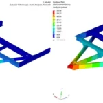
For robotics manufacturers and product development teams, the objective is not simply to produce a stress plot.
The objective is to answer a much more important question:
Will the robotic structure perform reliably under its actual operating conditions?
Why Perform FEA on a Robotic Arm Before Prototyping?
Physical prototypes are important in robotic hardware development. However, building and testing multiple physical iterations can become expensive, particularly when structural problems are discovered late in the development process.
FEA provides an opportunity to investigate these issues earlier.
A structural simulation can help engineers evaluate:
- Maximum stress
- Total deformation
- Deflection at the end effector
- Factor of safety
- Load paths
- Stress concentrations
- Joint and mounting loads
- Structural stiffness
- Fatigue life
- Natural frequencies
- Potential vibration problems
- Material utilization
- Weight reduction opportunities
This is particularly important for industrial robotic arms because small structural deflections can affect end-effector positioning and repeatability.
A robotic arm must therefore be designed around more than strength alone. Stiffness, mass, fatigue life, dynamic behavior, and the intended duty cycle all matter.
Caliber Technologies’ existing robotics engineering work similarly focuses on deflection, fatigue, dynamic loads, payload interaction, stress distribution, and design optimization for robotic arms.
1) Start With the Robotic Arm’s Operating Requirements
A useful FEA model begins before the geometry is imported into the solver.
The first step is understanding what the robot is expected to do.
Important inputs include:
Payload
What is the maximum payload at the end effector?
This should include the tooling or gripper where appropriate, not just the workpiece.
Reach
What is the maximum horizontal or vertical reach?
Longer links generally increase bending moments and can significantly influence deflection.
Operating speed
What are the acceleration and deceleration requirements?
A robot operating at low speed under steady loading may experience very different structural loads from a high-speed pick-and-place system.
Duty cycle
How frequently does the arm repeat its motion?
A structure experiencing millions of load cycles requires a different durability assessment from a prototype that will perform occasional laboratory movements.
Working envelope
Which positions create the highest structural loads?
The worst-case configuration is not necessarily the position where the robot looks most extended.
Environmental conditions
Temperature, humidity, contamination, vibration, and other operating conditions may influence material selection and component performance.
Defining these conditions early makes the subsequent simulation much more meaningful.
2) Build an Analysis-Ready CAD Model
The next step is preparing the robotic arm’s CAD geometry for analysis.
A production CAD model often contains details that are unnecessary for structural simulation.
Small fillets, cosmetic features, threads, logos, tiny holes, fastener details, and other features can increase model complexity without improving the engineering result.
At the same time, engineers should be careful not to remove features that significantly affect structural behavior.
Important areas to preserve include:
- Load-bearing interfaces
- Mounting points
- Joint connections
- Bearing seats
- Actuator interfaces
- Bolted connections
- Welded regions
- Major fillets
- Structural ribs
- Link interfaces
- End-effector mounting points
The goal is to create a model that is sufficiently detailed to represent the real load path while remaining efficient enough for practical simulation.
This is one reason the connection between CAD design and CAE is important in robotic hardware development.
A recent CAD-to-simulation workflow described by Onshape and NVIDIA demonstrates the industry’s broader move toward carrying mechanical design information into simulation rather than rebuilding models for every analysis stage.
3) Define Material Properties Correctly
Material selection directly affects the results of robotic arm structural analysis.
For a basic structural FEA model, engineers may need properties such as:
- Young’s modulus
- Poisson’s ratio
- Density
- Yield strength
- Ultimate tensile strength
For more advanced analysis, additional properties may be required.
These can include:
- Temperature-dependent properties
- Plastic stress-strain curves
- Fatigue data
- Damping characteristics
- Thermal expansion coefficients
- Composite material properties
For example, changing from a steel component to an aluminum component will alter mass, stiffness, strength, and natural frequency.
This means material selection cannot be separated from robotic arm design.
The right material is not necessarily the one with the highest strength.
The engineering objective may instead be to achieve an appropriate combination of:
Strength + stiffness + weight + manufacturability + cost + fatigue life.
4) Define Realistic Boundary Conditions
One of the most important parts of robotic arm FEA is defining how the structure is constrained.
An FEA model is only as useful as the assumptions behind it.
For example, completely fixing a large surface when the actual robot is mounted through a smaller bolt pattern can produce unrealistic structural behavior.
Similarly, applying a load directly to an entire end-effector surface when the actual load enters through a mounting interface may distort the results.
The model should represent the actual mechanical interfaces as closely as practical.
Typical boundary conditions can include:
- Fixed mounting interfaces
- Bearing constraints
- Joint connections
- Bolt loads
- Remote loads
- Contact interfaces
- Actuator loads
- Gravity
- Payload forces
- Inertial loads
The engineer should also document the assumptions.
That documentation becomes valuable later when the design changes or when simulation results need to be compared with physical testing.
5) Apply the Actual Robotic Loads
A common mistake in structural analysis is applying only the static payload.
A robotic arm does not simply hold a load.
It moves.
Acceleration and deceleration create additional inertial forces, while the robot’s configuration changes the moment arms and load paths.
Depending on the application, the analysis may need to consider:
Gravity loading
The weight of the links, actuators, tooling, and payload contributes to the structural load.
Payload loading
The end effector and workpiece can generate significant forces and moments.
Acceleration loading
Rapid movement increases inertial forces.
Deceleration loading
Sudden stops can generate significant transient loads.
Bending moments
Long robot links can experience substantial bending due to payload and self-weight.
Torsional loads
Twisting can become important around joints and drive interfaces.
Combined loading
Real operating conditions often involve multiple loads simultaneously.
Published robotic-arm studies use FEA under different loading conditions to evaluate structural response, demonstrating why the load case definition is central to the analysis.
6) Evaluate Stress and Deformation
Once the model and load cases are established, the first major evaluation is typically structural response.
Stress
Stress results help identify areas where the structure may approach or exceed allowable limits.
Typical areas requiring attention include:
- Joint interfaces
- Bolt locations
- Sharp geometric transitions
- Mounting brackets
- Actuator interfaces
- Thin sections
- Welded regions
- Link connections
But engineers should avoid looking only at the single highest numerical value.
A very localized peak around a sharp geometric feature or idealized constraint may require engineering interpretation rather than immediate redesign.
The load path and surrounding stress distribution matter.
Deformation
For robotic arms, deformation can be just as important as stress.
A component may have acceptable stress levels but still deflect too much for the required positioning accuracy.
This is especially relevant at the end effector.
Even relatively small structural deformation can become significant when the application requires precise positioning.
For that reason, robotic arm analysis should evaluate both:
Is the structure strong enough?
and:
Is the structure stiff enough?
These are different engineering questions.
7) Check Robotic Arm Stiffness
Stiffness is a critical design parameter for robotic manipulators.
Increasing stiffness can improve structural response, but simply adding material everywhere increases weight.
That creates a design trade-off.
More mass can increase actuator requirements and inertial loads.
Less mass can improve dynamic performance, but excessive weight reduction can reduce stiffness.
This is where simulation becomes particularly useful.
Engineers can compare design alternatives such as:
- Increasing wall thickness
- Adding ribs
- Changing cross-sectional geometry
- Modifying fillet radii
- Changing materials
- Relocating mounting points
- Redesigning joints
- Removing low-value material
The objective is not simply to make the arm stronger.
The objective is to achieve the required strength-to-weight and stiffness-to-weight performance.
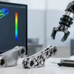
Research on lightweight robot design combines FEA with optimization methods specifically to improve stiffness and reduce structural mass.
8) Perform Fatigue Analysis for Repetitive Robot Motion
A robotic arm can experience thousands, hundreds of thousands, or millions of operating cycles.
That makes fatigue an important consideration for many industrial applications.
A component can remain below its static yield strength and still experience fatigue damage after repeated loading.
Fatigue analysis can help estimate:
- Expected fatigue life
- Critical locations
- Damage accumulation
- Sensitivity to load cycles
- Influence of stress concentration
- Effect of design changes
The appropriate fatigue methodology depends on the material, loading characteristics, stress history, surface condition, manufacturing process, and other factors.
For a production robot, fatigue analysis should therefore be connected to the actual operating cycle rather than treated as a generic calculation.
Caliber’s existing robotic-arm engineering work specifically addresses cyclic loads, fatigue damage, critical joints and long-term durability.
9) Consider Modal and Vibration Analysis
Static FEA does not tell the complete story for a moving robotic structure.
If a robot operates rapidly, vibration can become a significant engineering concern.
Modal analysis can identify the natural frequencies and mode shapes of the structure.
This information can then be compared with expected excitation sources such as:
- Motor operation
- Gear mesh
- Repeated acceleration
- Periodic motion
- External machinery
- Structural excitation
If an operating excitation is close to a structural natural frequency, resonance can become a concern.
This is why robotic arm development may require a combination of:
Static structural analysis + modal analysis + dynamic analysis + fatigue assessment.
Research into robotic-arm lightweighting has combined modal analysis and topology optimization to address both weight and vibration performance.
10) Use FEA to Optimize the Robotic Arm Design
The greatest value of FEA often comes after the first simulation.
Suppose the initial design shows:
- Excessive deformation near the end effector
- High stress around a joint
- Excess material in a low-stress region
- An undesirable natural frequency
- Excessive structural mass
The simulation results can guide the next design iteration.
Possible modifications include:
- Geometry changes
- Rib placement
- Wall thickness changes
- Material changes
- Joint redesign
- Local reinforcement
- Topology optimization
- Lightweighting
- Improved load paths
This creates a repeatable engineering loop:
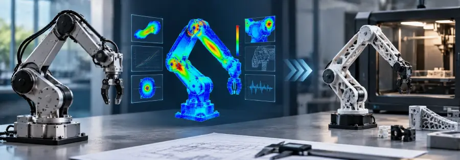
CAD → FEA → Results → Design Change → FEA → Validation
Studies of industrial robot arms have demonstrated how FEA can be used to support structural optimization and reduce unnecessary mass while maintaining stress and deformation requirements.
FEA Before Prototyping: What Should You Analyze?
A practical robotic arm simulation program may include several analysis types.
| Analysis | Main engineering question |
| Static Structural FEA | Can the structure withstand the applied loads? |
| Deformation Analysis | Will the arm deflect beyond acceptable limits? |
| Stress Analysis | Where are the critical stress regions? |
| Modal Analysis | What are the natural frequencies and mode shapes? |
| Fatigue Analysis | How long can the structure withstand repeated loading? |
| Thermal Analysis | Will temperature affect structural performance? |
| Dynamic Analysis | How does the structure behave under moving loads? |
| Design Optimization | Can mass be reduced while maintaining requirements? |
Not every project requires every analysis.
The right combination depends on the robot’s operating environment, motion profile, payload, materials, duty cycle, accuracy requirements, and manufacturing method.
When Should a Robotics Company Outsource FEA?
For robotics companies developing their own hardware, the question is often not whether FEA is useful.
It is whether the internal team has the time, software, engineering bandwidth, and specialist expertise to perform the analysis properly.
External FEA support can be useful when a company needs:
- Independent design verification
- Additional CAE capacity
- Rapid analysis of multiple design iterations
- Specialist structural engineering
- Fatigue and durability assessment
- Modal or vibration analysis
- Design optimization
- Support before physical prototyping
- Engineering support during product development
- Validation of an existing CAD design
This can be particularly valuable for robotics startups and growing OEMs that need engineering depth without building a large CAE team internally.
From CAD to FEA to a Better Robotic Hardware Design
Robotic arm development works best when mechanical design and engineering analysis are treated as connected activities.
The process can be structured around:
- Define requirements: Payload, reach, speed, acceleration, duty cycle and operating environment.
- Develop the mechanical design: Create the robot architecture, joints, links, mounting interfaces and end-effector connection.
- Prepare the CAD model: Remove unnecessary geometry while preserving important structural features.
- Define materials and interfaces: Establish material properties, joints, contacts and mounting conditions.
- Define load cases: Include payload, gravity, acceleration, deceleration, torque and other relevant loads.
- Perform FEA: Evaluate stress, deformation, stiffness and safety margins.
- Perform additional analysis: Where required, evaluate fatigue, vibration, modal behavior, thermal effects or dynamic loading.
- Optimize the design: Reduce weight, improve stiffness, address stress concentrations and improve structural efficiency.
- Validate the final design: Compare simulation predictions with physical testing where appropriate.
This approach allows engineering decisions to be made before expensive hardware iterations.
Need Robotic Arm FEA and Simulation Support?
For robotics companies, the value of FEA is not simply a colorful stress contour plot.
The real value is knowing where the design is likely to fail, where it can be improved, and whether the structure is ready for the next stage of development.
Caliber Technologies provides engineering simulation and product development support for applications where structural performance, durability, stiffness, and design optimization are critical.
For robotic hardware projects, engineering support can cover the path from CAD and mechanical design through structural FEA, fatigue, vibration analysis, simulation, optimization, and design validation.
If you are developing a robotic arm, robotic component, end effector, or other robotic hardware and need engineering analysis before prototyping, contact Caliber Technologies to discuss the project requirements.
FAQ
What is FEA in robotics?
FEA, or Finite Element Analysis, is a numerical engineering method used to evaluate how robotic structures and components respond to loads. It can be used to study stress, deformation, stiffness, fatigue, vibration, and other structural characteristics.
Why is FEA important for robotic arms?
FEA helps engineers identify structural weaknesses and excessive deformation before manufacturing physical prototypes. It can also support material selection, design optimization and fatigue assessment.
What loads should be considered in robotic arm FEA?
Depending on the application, analysis may include gravity, payload, acceleration, deceleration, bending, torsion, actuator forces, joint loads and other operational loads.
Can FEA predict robotic arm fatigue life?
Fatigue analysis can be used to estimate structural life under repeated loading when appropriate material data and representative load histories are available.
Can FEA reduce robotic arm weight?
Yes. FEA can identify areas where material contributes little to structural performance. Engineers can then use geometry changes or topology optimization to reduce mass while maintaining required stress and stiffness limits.
Should FEA be performed before building a robotic arm prototype?
For many structural robotics projects, performing FEA before prototyping can identify design issues early and reduce unnecessary physical iterations. The appropriate analysis depends on the project’s requirements and risk profile.