Why EV Inverter Busbars Overheat
In an electric vehicle inverter, busbars carry high currents between the DC link, power semiconductor modules and associated electrical connections. These conductors must handle demanding electrical loads within a restricted package, often close to heat-generating components.
A busbar can meet its nominal current rating and still develop localised overheating under certain operating conditions. The problem may appear around a bolted connection, a narrow conductor section, a bend or an interface between dissimilar components.
For EV engineering teams, these hotspots can create difficult validation problems. Temperatures may exceed local design limits even when the overall inverter temperature appears acceptable. Repeated thermal exposure can also accelerate insulation degradation, affect joint reliability and reduce the operating margin of nearby components.
Identifying the source requires more than checking the busbar’s cross-sectional area. Current distribution, electrical contact resistance, heat transfer and the surrounding enclosure all influence the final temperature.
What Causes Localised Heating in EV Inverter Busbars?
1. High Resistance at Electrical Connections
Bolted joints are potential hotspots because their electrical resistance depends on contact conditions, surface finish, contact pressure and assembly quality. Oxidation, surface contamination or insufficient clamping force can increase resistance at the interface.
The resulting heat generation follows the relationship (P = I^2R). Even a small increase in resistance can produce substantial local heating when current is high.
If the connection temperature rises disproportionately compared with the rest of the conductor, engineers should investigate the joint interface rather than assuming the entire busbar is undersized.
2. Uneven Current Distribution
Busbar geometry affects how current distributes through the conductor. Changes in width, thickness, bends, branch connections and proximity to adjacent conductors can create non-uniform current density.
This becomes particularly important in compact inverter designs where multiple electrical paths must fit within a limited enclosure. Local current concentration can increase resistive losses and produce temperature differences that are not captured by a simple average-current calculation.
3. Restricted Heat Dissipation
A busbar’s temperature depends on how effectively it transfers heat to surrounding structures and the environment. Limited airflow, nearby heat sources, insulating supports and restricted contact with mounting structures can reduce heat removal.
The same conductor may therefore operate at different temperatures in two enclosure configurations. A design assessed in isolation may not represent the thermal conditions inside the assembled inverter.
How Engineering Analysis Identifies the Root Cause
When physical testing reveals a hotspot, changing the busbar dimensions immediately may not resolve the underlying problem. The investigation should establish whether the dominant cause is electrical resistance, current distribution, heat transfer or a combination of these factors.
Electrical Loss and Current Distribution Analysis
The first step is to assess current paths, conductor geometry and local electrical losses under representative operating conditions. Where necessary, electrical simulation can identify areas with elevated current density and resistive heating.
The analysis should account for relevant operating currents and duty cycles rather than relying only on a single nominal rating. Connection resistance should also be considered where reliable measurements or suitable engineering data are available.
Thermal Simulation of the Assembled Inverter
Thermal analysis can assess how heat generated in the busbar and its connections moves through the assembly. The model should represent relevant contact interfaces, surrounding components, enclosure materials and cooling conditions.
This helps determine whether the hotspot originates within the conductor or is aggravated by poor heat dissipation. It can also reveal whether neighbouring components are exposed to temperatures above their allowable limits.
For more complex configurations, electrical loss calculations and thermal simulation can be coupled so that heat generation reflects the electrical behaviour of the design.
Correlation With Physical Test Results
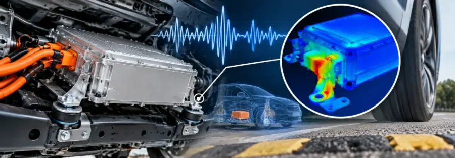
Simulation findings should be compared with available temperature measurements and electrical test data. Infrared thermography can help identify surface temperature patterns, while suitable contact-resistance and current measurements can support diagnosis.
Differences between predicted and measured temperatures may indicate uncertain contact resistance, incorrect boundary conditions or an incomplete representation of the assembled system. Resolving these differences improves confidence in proposed design changes.
Design Changes That Can Reduce Busbar Hotspots
The appropriate correction depends on the identified cause.
- Improve joint performance: Review contact surfaces, clamping requirements, joint geometry and assembly tolerances where connection resistance is responsible for excessive heating.
- Revise conductor geometry: Assess whether changes to thickness, width, bends or current paths can reduce local current concentration without creating packaging conflicts.
- Improve heat transfer: Evaluate mounting interfaces, thermal paths, spacing and enclosure cooling conditions.
- Review operating conditions: Assess transient current peaks, repeated high-load operation and relevant duty cycles instead of validating only steady-state nominal conditions.
- Revalidate the complete assembly: Confirm that a proposed change does not create new problems involving packaging, electrical clearances, mechanical support or neighbouring components.
Increasing busbar thickness alone is not always the best solution. It can add mass, consume valuable space and leave a high-resistance joint unchanged. Engineering changes should address the cause of the hotspot and be checked against the inverter’s wider design requirements.
When EV Engineering Teams Need Specialist Simulation Support
Busbar thermal problems can become difficult to resolve when several factors interact, particularly in compact inverter assemblies with limited cooling capacity and demanding current profiles.
An external engineering team can help investigate the issue when internal resources are limited, prototype testing repeatedly reveals unexplained hotspots, or design changes require further analysis before another validation cycle.
Caliber Technologies supports engineering teams with CAE simulation, product design and engineering analysis. For inverter busbar investigations, the scope can be defined around the available geometry, electrical loading, material data and test evidence. Electrical and thermal modelling requirements should be agreed according to the specific project and the capabilities required.
The objective is to identify the dominant heat source, evaluate feasible design changes and provide engineering evidence before committing to another prototype iteration.
Discuss Your EV Inverter Engineering Challenge
Are busbar connections overheating, or are measured inverter temperatures exceeding simulation predictions? Caliber Technologies can discuss the available design data and determine an appropriate engineering analysis scope.
Contact: operations@thecalibertech.com