Why Vibration Is a Reliability Challenge for EV Power Electronics
Electric vehicles expose electronic assemblies to mechanical loads generated by road inputs, vehicle structures, powertrain operation and component mounting. These loads can reach inverter control boards, onboard charger electronics and other power electronics assemblies.
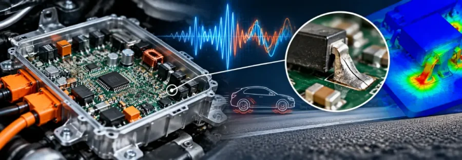
Although a circuit board may pass initial functional testing, repeated vibration can cause mechanical damage over time. Solder joints may develop fatigue cracks, component leads can experience repeated bending, and heavy components can place additional loads on their mounting points.
The challenge becomes more difficult when a new EV platform has limited prototype test data. Engineering teams must determine whether the board, its mounting arrangement or the surrounding enclosure is responsible for excessive vibration response.
For EV developers, resolving these problems may require structural dynamics analysis and fatigue assessment alongside physical testing. Replacing damaged components without identifying the mechanical cause can leave the underlying reliability issue unresolved.
What Causes Vibration-Related Damage in Circuit Boards?
1. Circuit Board Resonance
Every circuit board has natural frequencies and corresponding vibration modes. When excitation occurs near one of these frequencies, the board can experience amplified vibration response.
The resulting deformation depends on board dimensions, thickness, material properties, component placement, mounting locations and support stiffness.
A board that performs adequately during a basic vibration check may respond differently when installed in a vehicle enclosure with different mounting conditions. Resonance can increase local bending and cyclic strain around sensitive components or solder connections.
Modal analysis helps identify natural frequencies and mode shapes. Engineers can then compare these results with the expected excitation environment and investigate areas where vibration response may be excessive.
2. Fatigue at Solder Joints and Component Connections
Solder joints connect electronic components to the printed circuit board and must tolerate mechanical strain during operation. Repeated board bending can place cyclic loads on these connections.
The risk depends on several factors, including component mass, package geometry, solder-joint design, board deformation and the vibration environment. Large or heavy components can generate significant local loading, particularly when their supports are insufficient.
Fatigue assessment should consider the expected loading cycles and the relevant failure mechanism. A global board stress result alone may not accurately represent the local behaviour of a solder joint.
Where detailed solder-joint reliability is the main concern, the analysis may need to account for local geometry, material behaviour and suitable fatigue data. Structural simulation can identify critical regions, but detailed life prediction requires an appropriate modelling method and validated inputs.
3. Inadequate Mounting and Support Stiffness
Mounting arrangements influence how vibration enters a circuit board. Widely spaced supports, flexible brackets or unsuitable attachment locations can allow excessive bending.
The enclosure also matters. Changes in housing stiffness or mounting design can alter the vibration response of the complete assembly.
Engineers should therefore assess the board together with its relevant supports and enclosure interfaces rather than treating the PCB as an isolated component.
4. Heavy Components and Localised Dynamic Loading
Power electronics boards may carry transformers, inductors, capacitors, connectors and other components with different masses and mounting arrangements.
During vibration, these components can apply inertial loads to the board and their attachment points. A component that is mechanically secure under static conditions may still create high cyclic loads when the assembly vibrates.
Component mass, location and support design should be reviewed alongside the board’s dynamic response.
How Engineering Simulation Helps Identify the Root Cause
Modal Analysis to Identify Critical Frequencies
A modal analysis estimates the natural frequencies and mode shapes of the circuit board and its supporting structure. The results help identify whether a flexible mode could coincide with the expected excitation frequencies.
The model should represent realistic mounting conditions and include component masses where they significantly affect the response.
This provides an initial basis for reviewing board stiffness, support locations and possible design changes before further physical testing.
Harmonic and Random Vibration Analysis
The appropriate dynamic analysis depends on the available loading information.
Harmonic analysis can evaluate response to sinusoidal excitation at specified frequencies. Random vibration analysis can estimate response under broadband excitation when a suitable power spectral density profile is available.
These methods help engineers assess displacement, acceleration and stress or strain response across the assembly. The resulting hotspots can guide further investigation of component connections and mounting regions.
The analysis should use representative boundary conditions and loading profiles. Incorrect support assumptions can produce misleading predictions of vibration response.
Fatigue Assessment and Test Correlation
When the dynamic response indicates potentially damaging cyclic loading, fatigue assessment can help estimate the risk of repeated-load failure. The method should reflect the relevant failure mechanism, material data and loading history.
Where physical test results are available, measured acceleration and strain data can help assess whether the model represents the real assembly. Differences between simulation and testing may point to incorrect mounting stiffness, missing component mass, uncertain damping or an incomplete excitation profile.
Simulation should support the investigation, not replace the required qualification and reliability testing.
Design Changes That Can Reduce Vibration-Related Failure
The appropriate correction depends on the failure mechanism identified during analysis.
- Increase board stiffness: Review board thickness, geometry and support locations where excessive bending drives the response.
- Revise mounting arrangements: Assess attachment spacing, bracket stiffness and enclosure interfaces to reduce unwanted vibration amplification.
- Review heavy component support: Evaluate mechanical retention for components that impose significant inertial loads on the board.
- Address critical frequency response: Where appropriate, modify stiffness or mass distribution to change natural frequencies and reduce the response to expected excitation.
- Validate fatigue performance: Reassess critical connections under representative loading and confirm design changes through suitable testing.
Design changes should not be made solely to move a natural frequency. The revised assembly must still meet packaging, thermal, electrical, manufacturing and reliability requirements.
When EV Teams Need Specialist Engineering Support
Vibration-related electronic failures can require several rounds of investigation, especially when the damage is intermittent or appears only under specific operating conditions.
Specialist engineering support may be useful when an EV startup is experiencing repeated circuit board failures, cannot identify the source of excessive vibration, or needs simulation support before committing to another prototype build.
Caliber Technologies provides engineering services in CAE simulation, structural analysis and durability assessment. Depending on the project requirements and available data, an investigation can focus on board dynamics, mounting stiffness, vibration response and structural fatigue.
The scope should be agreed around the actual failure mechanism. Detailed solder-joint life prediction, for example, requires suitable local modelling methods and material or reliability data rather than relying on a general structural simulation alone.
Discuss Your EV Engineering Requirements
If an EV power electronics assembly is experiencing vibration-related damage, Caliber Technologies can discuss the available CAD models, mounting details, test results and engineering requirements to determine a suitable analysis approach.