A robotic mechanism can look correct in CAD and still fail to perform as expected once it is built.
The structure may be too flexible. A joint may see higher loads than expected. An arm may vibrate at a particular operating speed. A bracket may pass a basic static load case but fail under repeated loading. A heavier end effector may change the system’s dynamic behavior.
These problems become expensive when they are discovered after manufacturing.
Robotic hardware design validation is the process of checking whether the mechanical design can meet its required structural, dynamic, functional and operating requirements before the hardware is committed to production.
For physical robotics products, validation is not a single simulation.
It is a combination of engineering calculations, CAD review, structural analysis, dynamic analysis, design verification and, where required, physical prototype testing.
The objective is straightforward:
Find design problems while they are still inexpensive to fix.
What is robotic hardware design validation?
Robotic hardware design validation evaluates whether a robot’s physical design can perform its intended function under realistic operating conditions.
Depending on the product, validation can include:
- Structural FEA
- Stress and strain analysis
- Deflection analysis
- Load analysis
- Fatigue analysis
- Modal analysis
- Vibration analysis
- Thermal analysis
- Joint and actuator loading
- Kinematic verification
- Dynamic simulation
- Design-for-manufacturing review
- Prototype testing
- Test-to-simulation correlation
The exact combination depends on the robot.
A lightweight robotic arm, an autonomous mobile robot chassis, a robotic gripper and an industrial actuator assembly do not have the same validation requirements.
The validation plan should therefore begin with the engineering requirements, not with a predefined list of simulations.
Why robotics hardware needs validation before manufacturing
Robotics hardware is exposed to changing loads and operating conditions.
A robot may experience:
- Static payload
- Dynamic payload
- Acceleration and deceleration
- Repeated cycles
- Impact loads
- Vibration
- Thermal loads
- Joint torque
- External forces
- Tool loads
- Mounting loads
The worst structural condition is not necessarily the robot’s maximum payload.
A particular joint configuration may create a larger bending moment.
A rapid motion may create a higher dynamic load than a stationary payload.
An extended arm configuration may produce substantially more deflection than a compact configuration.
A new end effector may shift the center of mass and increase actuator torque.
These conditions need to be considered before the design is released.
Recent robotic-arm development work demonstrates this simulation-to-test approach. One 2026 study combined mechanical modeling, kinematic analysis, FEA, dynamic simulation and physical prototype testing, then compared simulation behavior with experimental results.
What should be validated in a robotic hardware design?
There is no single validation checklist that applies to every robot.
However, a physical robotics product commonly needs to answer several fundamental questions.
1. Is the structure strong enough?
The design needs to withstand the expected loads without unacceptable stress, yielding or failure.
2. Is the structure stiff enough?
Strength and stiffness are different requirements.
A robotic arm can remain below its material strength limit while still deflecting enough to affect positioning accuracy.
3. Will it survive repeated operation?
A component that survives one maximum load may not survive millions of operating cycles.
Fatigue can therefore become important for joints, links, brackets and other repeatedly loaded components.
4. Will it vibrate during operation?
A structure can pass static FEA and still have a resonance problem.
Modal and vibration analysis can identify natural frequencies and structural modes before physical testing.
5. Can the actuators handle the required loads?
Mechanical validation should also consider the loads transmitted to motors, gearboxes, bearings and joints.
6. Can the design actually be manufactured?
A design that performs well in simulation still needs to satisfy manufacturing, assembly, tolerance and inspection requirements.
7. Does the physical prototype behave like the simulation?
Prototype testing provides an opportunity to compare predicted and measured behavior and identify model assumptions that need refinement.
Start validation with engineering requirements
The first step should not be opening an FEA package.
It should be defining what the robot is expected to do.
For example, a robotic arm specification may include:
- Payload
- Reach
- Operating speed
- Acceleration
- Cycle time
- Positioning accuracy
- Repeatability
- Number of cycles
- Operating temperature
- Mounting condition
- End-effector mass
- Expected external loads
These requirements determine the load cases and validation methods.
Consider a robotic arm designed for a 10 kg payload.
That number alone is not enough to define the structural analysis.
The engineering team also needs to know:
- Where is the payload located?
- What is the maximum reach?
- Which joint configuration creates the highest moment?
- What acceleration is expected?
- How quickly does the arm stop?
- How many cycles will it perform?
- What is the mass of the end effector?
- Is the payload center of gravity offset?
- Is the arm expected to maintain a specific positional tolerance?
The validation model should represent these actual operating requirements.
Build realistic robotic hardware load cases
A good validation study is only as useful as its load cases.
For a robotic arm, load cases may include several configurations rather than one maximum-load condition.
Static payload case
This evaluates structural behavior under the robot’s stationary payload.
It can help identify:
- Maximum stress
- Deflection
- Critical joints
- Critical links
- Load paths
Extended-reach case
The arm is evaluated in a configuration where the payload produces a large moment about the base or joint.
This can be more demanding than a compact configuration.
Acceleration case
Dynamic acceleration increases the effective loads acting on components.
This can be particularly important for high-speed robots.
Deceleration case
Rapid stopping can create significant inertial loads.
The direction and magnitude of those loads depend on the motion profile and mass distribution.
Offset payload case
A payload whose center of mass is away from the joint axis can create additional torque.
This should be considered when the actual end effector is not symmetric.
Combined loading case
Real hardware can experience multiple loads simultaneously.
For example:
Payload + acceleration + gravity + external tool force
can produce a more demanding condition than any one load individually.
The exact load combinations should be derived from the robot’s operating envelope.
Structural FEA for robotic hardware validation
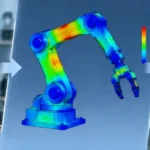
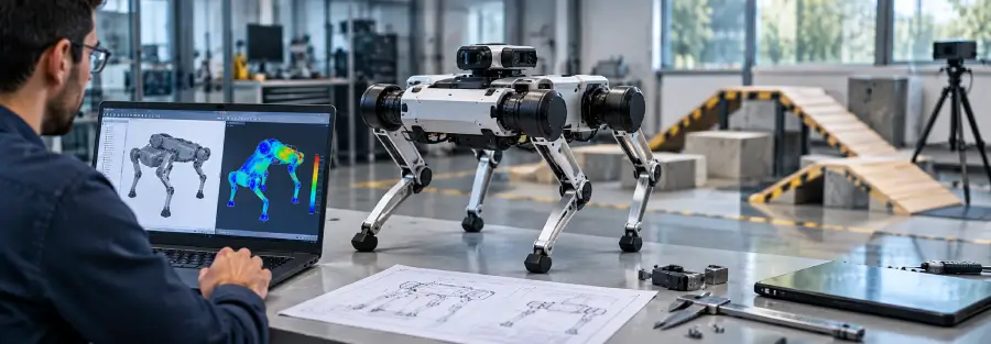
Finite element analysis is one of the most useful tools for evaluating the mechanical structure before manufacturing.
For robotics hardware, structural FEA can investigate:
- Von Mises stress
- Principal stress
- Strain
- Total deformation
- Joint loads
- Contact pressure
- Structural stiffness
- Safety margins
The important point is that FEA should answer a design question.
A contour plot by itself is not validation.
The useful question is:
Does the simulated response satisfy the engineering requirement under the relevant operating load?
For example:
If the maximum allowable end-effector displacement is 0.5 mm, the analysis should evaluate whether the actual design remains within that requirement under the specified payload and configuration.
That is much more useful than simply reporting a stress value.
Robotic arm deflection can be as important as strength
Deflection is especially important for robots because positioning performance can be affected by structural compliance.
Suppose a robotic arm remains well below the material’s yield strength.
From a strength perspective, the design may appear acceptable.
But if the end effector moves several millimeters under load, the robot may not meet the required positioning accuracy.
This is why structural validation should consider both:
Strength
and
Stiffness
The existing Caliber article on robotic arm deflection and fatigue can support this part of the topic and should be linked here as a related engineering analysis.
Fatigue validation for robotic mechanisms
Robotic hardware often performs the same motion thousands or millions of times.
That makes repeated loading important.
Fatigue analysis can help investigate whether a component is likely to withstand its expected operating life.
Potential fatigue-sensitive areas include:
- Arm links
- Joint brackets
- Shafts
- Mounting plates
- Gear components
- Welded structures
- Bolted interfaces
- End-effector mounts
The relevant fatigue load is not necessarily the maximum static load.
A component may experience a lower load repeatedly for a very large number of cycles.
The validation process should therefore establish a realistic load spectrum where the application requires fatigue assessment.
This is particularly important when a robotic system is intended for continuous industrial operation.
Modal and vibration validation
Structural strength does not guarantee dynamic performance.
A robot can survive its maximum load and still experience excessive vibration.
Modal analysis can identify:
- Natural frequencies
- Mode shapes
- Flexible components
- Structural modes
- Potential resonance regions
The next step may be frequency-response or harmonic analysis when the operating excitation is known.
For example, the engineering team may need to investigate whether:
- Motor excitation
- Gearbox frequencies
- Motion cycles
- Base vibration
- Operating speed
can interact with structural modes.
This is why modal analysis should be considered part of the validation process for high-speed or vibration-sensitive robotics hardware.
Recent research continues to combine experimentally validated FEA with dynamic and harmonic analysis for robotic-arm structures.
Joint and actuator validation
The robot’s links are only part of the mechanical system.
The joints need to be evaluated as well.
Depending on the architecture, joint validation may include:
- Motor torque
- Gearbox torque
- Bearing loads
- Shaft stress
- Gear loads
- Joint stiffness
- Thermal behavior
- Repeated-cycle loading
A mechanically strong arm can still have an undersized actuator.
Similarly, increasing structural stiffness can increase actuator requirements.
This is why hardware validation should consider the relationship between:
Structure → Joint → Actuator → Payload
rather than validating each component independently.
Validate the robot across its working envelope
One of the biggest mistakes in robotic hardware analysis is validating only one configuration.
A multi-axis robot changes its mechanical loading as it moves.
For an articulated arm, the worst condition may occur when:
- The arm is fully extended
- The payload is at maximum reach
- Multiple axes are accelerating
- The tool has an offset center of mass
- The arm is moving against an external force
Another configuration may be more critical for a different requirement.
For example:
Configuration A: maximum base moment
Configuration B: maximum joint torque
Configuration C: maximum end-effector deflection
Configuration D: maximum vibration response
There may not be one universal worst-case position.
The validation plan should therefore cover the relevant operating envelope.
CAD review is part of hardware validation
Simulation does not replace engineering design review.
The CAD model should also be checked for:
- Interference
- Joint clearance
- Fastener access
- Assembly sequence
- Tool access
- Bearing installation
- Cable routing
- Manufacturing access
- Inspection access
- Serviceability
A structurally sound part that cannot be assembled efficiently is still a poor hardware design.
For robotics companies moving from concept to production, CAD validation and CAE validation should therefore progress together.
Design for manufacturing should happen before validation is closed
A simulation may identify an ideal structural geometry that is difficult or expensive to manufacture.
The final design needs to consider its intended manufacturing process.
For example:
CNC-machined components
Consider:
- Tool access
- Minimum internal radii
- Wall thickness
- Machining time
- Datum strategy
Sheet-metal components
Consider:
- Bend radii
- Bend sequence
- Flat-pattern constraints
- Weld locations
Cast components
Consider:
- Draft
- Wall thickness
- Fillets
- Parting lines
Additive-manufactured components
Consider:
- Build orientation
- Support requirements
- Anisotropic material behavior
- Post-processing
- Surface finish
A design should therefore be validated not only as a mathematical geometry but as a component that can actually be produced.
Prototype testing should verify the critical assumptions
Simulation is performed before manufacturing precisely because it is cheaper to modify a virtual design.
But once a prototype exists, physical testing becomes valuable.
Testing can be used to measure:
- Displacement
- Strain
- Natural frequencies
- Vibration
- Temperature
- Actuator torque
- Position accuracy
- Repeatability
- Cycle life
The purpose is not necessarily to reproduce every simulation result exactly.
The objective is to determine whether the model represents the physical hardware closely enough to support the engineering decision.
A recent 6-DOF robotic-arm study used FEA during design and then fabricated a prototype for experimental evaluation. The reported testing also exposed vibration and load-dependent tracking limitations that were not apparent from the structural design alone.
That is exactly why simulation and testing should be treated as complementary activities.
Simulation-to-test correlation
Suppose an FEA model predicts a certain natural frequency.
Physical modal testing produces a different value.
That difference does not automatically mean the simulation is useless.
It can indicate that one of the model assumptions needs improvement.
Possible sources include:
- Joint stiffness
- Boundary conditions
- Material properties
- Component mass
- Fastener behavior
- Contact conditions
- Manufacturing variation
The model can then be updated and the analysis repeated.
This creates a useful engineering loop:
Simulation → Prototype → Test → Correlation → Model update → Design improvement
For complex robotics hardware, this can become an important part of the product-development process.
What should a robotic hardware validation report contain?
A useful validation report should make the engineering decision easy to understand.
Depending on the project, it may include:
Design definition
- CAD revision
- Materials
- Mass properties
- Major assumptions
Requirements
- Payload
- Speed
- Acceleration
- Deflection limit
- Stress limit
- Operating life
- Temperature range
Load cases
- Static
- Dynamic
- Payload
- External forces
- Worst-case configurations
Simulation methodology
- FEA approach
- Boundary conditions
- Contacts
- Mesh strategy
- Material models
Results
- Stress
- Deformation
- Strain
- Safety margin
- Natural frequencies
- Mode shapes
- Thermal results where applicable
Design assessment
- Requirement met
- Requirement not met
- Design change required
- Additional analysis required
Physical validation
- Test method
- Instrumentation
- Measured results
- Simulation comparison
- Deviations
- Final conclusion
The objective is not to create a large report.
The objective is to provide enough evidence to support a design-release decision.
Common mistakes in robotic hardware validation
Validating only the maximum payload
Maximum payload is only one operating condition.
Configuration, reach, acceleration and tool geometry can change the actual load significantly.
Checking stress but ignoring deflection
A component can be structurally strong but too flexible for the robot’s accuracy requirement.
Running FEA on unrealistic boundary conditions
Incorrect constraints can make the simulation appear safer or more conservative than the real hardware.
Ignoring joint stiffness
The arm links may be stiff while the joint assembly remains the dominant source of compliance.
Validating only one robot configuration
Different positions can create different critical load cases.
Optimizing weight without checking dynamics
Removing material can change stiffness and natural frequencies.
Treating simulation as the final proof
Simulation is based on assumptions.
Physical testing is often required to confirm the actual behavior of the finished hardware.
When should robotic hardware validation begin?
Validation should begin while the design is still changing.
It does not need to wait until the CAD model is completely finished.
A practical development sequence can look like this:
Concept
↓
Engineering requirements
↓
Preliminary CAD
↓
Load and actuator calculations
↓
Structural FEA
↓
Design iteration
↓
Modal / vibration analysis
↓
Optimization
↓
Detailed CAD
↓
DFM review
↓
Prototype
↓
Physical testing
↓
Simulation-to-test correlation
↓
Final design release
This allows the engineering team to identify problems before they become manufacturing problems.
How Caliber can support robotic hardware validation
For robotics companies developing physical products, validation often requires several engineering disciplines to work together.
Caliber can position its robotics engineering capability around this complete mechanical analysis workflow:
- CAD and mechanical design
- Structural FEA
- Stress and deformation analysis
- Fatigue analysis
- Modal analysis
- Vibration analysis
- Design optimization
- Product development support
- Design validation
- Engineering analysis before prototyping
The value is not simply producing an FEA report.
The more useful outcome is helping the design team answer:
Can we manufacture this design with confidence?
Will it withstand the expected loads?
Will it remain sufficiently stiff?
Will vibration affect performance?
Will the design survive the expected operating cycles?
What needs to change before we build the next prototype?
That is the role of simulation-led hardware validation.
Conclusion
Robotic hardware validation is most valuable when it is treated as part of the design process rather than as a final inspection step.
A robot needs more than a structurally strong CAD model.
It needs to meet its load, stiffness, dynamic, fatigue, manufacturing and operating requirements.
That requires a combination of engineering calculations, simulation and physical testing.
For a robotic arm, this may mean combining structural FEA with deflection, fatigue, modal and vibration analysis. For other robotic hardware, the validation plan may focus more heavily on joints, thermal behavior, actuator loads, chassis strength or repeated-cycle performance.
The right approach depends on the actual product requirements.
The earlier those requirements are translated into engineering load cases and validation criteria, the more opportunity the development team has to solve problems before they reach manufacturing.
If your robotics hardware is still in the design stage, Caliber Technologies can support the engineering analysis required to evaluate the structure, identify design risks and prepare the hardware for prototype and validation testing.
Frequently Asked Questions
What is robotic hardware design validation?
Robotic hardware design validation is the engineering process used to verify that a robot’s physical design meets its structural, dynamic, thermal, functional and operating requirements before production.
How is a robotic arm design validated?
A robotic arm can be validated using engineering calculations, CAD review, structural FEA, stress and deflection analysis, fatigue analysis, modal analysis, dynamic simulation and physical prototype testing, depending on the application.
Is FEA enough to validate a robotic arm?
Not always. FEA can predict structural behavior under defined assumptions, but physical testing may be required to verify the actual hardware and correlate the simulation model.
What should be tested on a robotic arm prototype?
Depending on the requirements, testing can include load capacity, deflection, vibration, natural frequencies, actuator performance, positioning accuracy, repeatability, temperature and cycle life.
Why is robotic arm deflection important?
Deflection can directly affect end-effector positioning and repeatability. A robot can remain structurally safe while still being too flexible to meet its accuracy requirements.
When should FEA be performed during robot development?
FEA should be introduced while the mechanical design is still flexible enough to change. Early analysis can identify structural problems before tooling and manufacturing decisions become expensive to change.
Can simulation reduce robotic hardware prototypes?
Simulation can reduce the number of physical design iterations by identifying structural and dynamic problems before manufacturing. It does not eliminate the need for physical validation when testing is required.
What is the difference between verification and validation?
Verification generally asks whether the design meets specified requirements using defined methods. Validation asks whether the finished product actually performs as intended in its intended application. The exact terminology can vary between engineering organizations and quality systems.