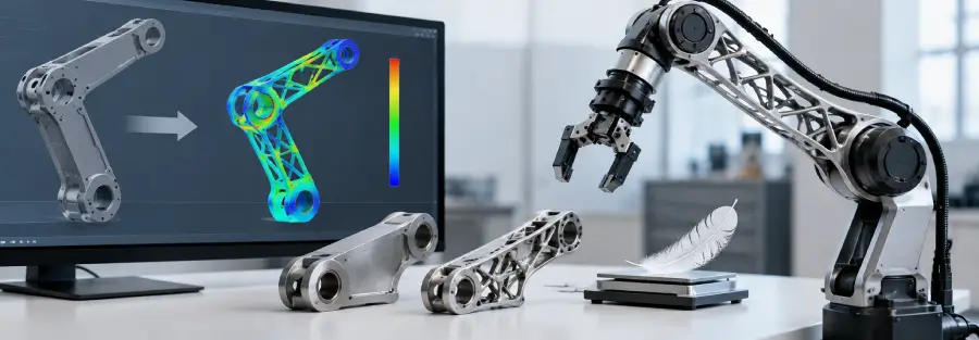
A robotic arm is often caught between two competing requirements: it needs to be stiff enough to carry its payload accurately, but light enough to move quickly without placing unnecessary demand on its actuators.
Adding material can make a structure stronger and stiffer, but it also increases mass. That additional mass has to be accelerated and decelerated every time the robot moves. It can increase actuator torque requirements, affect dynamic response, and reduce the useful payload that the system can carry.
Removing material creates the opposite problem. A lighter arm may require less actuator effort, but excessive material removal can increase deformation, reduce stiffness, create local stress concentrations, or introduce vibration problems.
This makes robotic arm design optimization more complicated than simply trying to make the structure as light as possible.
The engineering objective is usually to find a better balance between mass, stiffness, strength, fatigue life, dynamic behavior, manufacturability, and cost.
Finite Element Analysis (FEA), topology optimization, parametric optimization, and structural simulation can help engineers make these decisions before committing to a final hardware design.
For robotics manufacturers developing a new arm, improving an existing robot, or trying to reduce the mass of a structural component, the important question is not simply:
How much weight can we remove?
It is:
How much weight can we remove while keeping the robotic arm within its required structural and performance limits?
Why Weight Matters in Robotic Arm Design
The structural mass of a robotic arm does not remain stationary during operation. The arm and its components have to be accelerated, decelerated, and repositioned repeatedly.
This creates an important relationship between the mechanical structure and the actuation system.
A heavier link can increase the torque required from the actuator. That additional torque can influence motor and gearbox selection, power requirements, thermal loading, and dynamic performance.
The effect becomes particularly important in a serial robotic arm because the mass of one component can influence the loads experienced by components further down the kinematic chain.
This is one reason lightweight robot design has received significant attention in industrial robotics research. Studies on lightweight serial robots have examined the relationship between structural mass, stiffness, deformation, and the resulting behavior at the end effector.
Weight reduction therefore should not be treated as an isolated CAD exercise.
A change to one structural component can affect the rest of the system.
Why Simply Making a Robotic Arm Thinner Does Not Work
One of the easiest ways to reduce weight is to reduce wall thickness or remove material from a component.
It is also one of the easiest ways to create a structural problem.
Consider a robotic arm link carrying a payload at its end. If material is removed without considering the load path, the component may become more flexible. The resulting deformation can increase at the end effector even if the component still has an acceptable factor of safety against yielding.
For a precision robot, that may be unacceptable.
There is also another issue.
The highest stress does not necessarily occur where the component looks weakest from a visual inspection. Loads travel through the structure according to its geometry, supports, joints, and loading conditions. A small geometric change around a mounting interface can have a larger effect on stress than removing a much larger volume of material elsewhere.
This is why robotic arm design optimization should be driven by engineering analysis rather than weight reduction alone.
What Should Be Optimized in a Robotic Arm?
Weight is only one possible optimization objective.
Depending on the application, engineers may optimize for:
- Minimum structural mass
- Maximum stiffness
- Minimum end-effector deformation
- Maximum strength-to-weight ratio
- Maximum stiffness-to-weight ratio
- Reduced actuator load
- Improved natural frequency
- Reduced vibration
- Improved fatigue life
- Reduced material consumption
- Improved manufacturability
These objectives can also conflict with one another.
For example, reducing mass can lower structural stiffness. Increasing stiffness may require additional material. A topology optimization that produces an excellent theoretical structure may be difficult or expensive to manufacture.
A practical optimization therefore needs to consider the complete product, not just the FEA result.
Start With the Actual Operating Conditions
A robotic arm cannot be optimized properly without first understanding how it will operate.
The analysis should establish the conditions that the structure must satisfy.
These may include:
- Payload: What is the maximum mass carried by the end effector?
- Reach: What is the maximum distance between the relevant joints and the payload?
- Acceleration: How quickly does the arm need to move?
- Deceleration: What happens when the arm stops or changes direction?
- Duty cycle: How many operating cycles are expected during the product’s service life?
- Workspace: Which configurations will the robot actually use?
- Accuracy requirements: How much end-effector deformation can the application tolerate?
- Environment: Are temperature, vibration, contamination, or other conditions relevant?
These inputs determine the load cases and constraints used during structural optimization.
A design that is optimal for a static payload at one arm position may not be optimal when the same arm is evaluated across several configurations and operating conditions.
Research into topology optimization of robotic arms has specifically highlighted the difficulty of optimizing robot structures because the loading and configuration can change during motion. More recent work has also considered time-varying loads across multiple positions rather than optimizing a component for a single static configuration.
Identify the Components That Actually Matter
Not every part of a robotic arm contributes equally to structural performance.
The engineering team should first identify the components that have a significant effect on:
- Structural stiffness
- End-effector deflection
- Overall mass
- Joint loading
- Natural frequency
- Load transfer
These could include the primary arm links, forearm structures, joint housings, brackets, actuator mounts, base structures, or end-effector interfaces.
The most effective optimization opportunity is often found in a component that has both significant mass and significant influence on system performance.
Optimizing a small bracket may produce a visually impressive percentage reduction in that individual component’s mass while having almost no effect on the overall robot.
The better question is:
What component gives us the greatest system-level improvement for the engineering effort invested?
Use FEA Before Optimization
A baseline structural analysis should normally be performed before changing the geometry.
This provides a reference against which the optimized design can be compared.
The baseline model can show:
- Maximum stress
- Deformation
- Critical load paths
- Stiffness
- Reaction forces
- High-stress regions
- Low-stress regions
- Structural mass
- Natural frequencies, where relevant
This information helps engineers understand where material is doing useful structural work and where there may be an opportunity to redesign the geometry.
It also prevents a common mistake: optimizing the design without knowing whether the original problem was actually structural.
For example, if the arm already has very low deformation but excessive mass, the optimization strategy may be different from a design where deformation is already close to the allowable limit.
The Goal Is Not to Remove Material Everywhere
Good structural optimization usually creates a more efficient load path rather than simply making every section thinner.
Material should remain where it contributes to carrying the loads.
It can potentially be removed from regions that have relatively low structural utilization, provided that the resulting geometry remains within the required constraints.
This is one of the principles behind topology optimization.
Instead of asking an engineer to manually decide where every pocket, rib, hole, or reinforcement should go, topology optimization can search a defined design space subject to specified objectives and constraints.
For example, an optimization problem might seek to minimize mass while maintaining:
- Maximum allowable stress
- Maximum allowable displacement
- Required stiffness
- Manufacturing constraints
- Minimum member size
- Design interfaces
- Load-bearing regions
Research involving robotic arms has demonstrated the use of topology optimization and FEA to reduce structural mass while maintaining defined stress and deformation limits.
Topology Optimization for Robotic Arms
Topology optimization is particularly useful when the existing geometry is not necessarily the best structural arrangement.
A conventional CAD redesign typically starts with the existing shape and modifies it.
Topology optimization can approach the problem differently.
The engineer defines a design space and specifies regions that must remain, such as mounting interfaces or joint connections. The solver then determines how material can be distributed within the available space to satisfy the defined objectives.
For a robotic arm, this can produce structures with:
- Internal ribs
- Curved load paths
- Open sections
- Truss-like structures
- Reduced material in low-load regions
- More efficient structural transitions
However, the raw optimization result should not automatically become the production CAD model.
The optimized result needs engineering interpretation.
A topology optimization result may contain thin members, complex geometry, sharp transitions, or shapes that are difficult to manufacture. The engineering team must convert the result into a practical design.
That redesign should then be analyzed again.
The process is therefore not:
Topology optimization → Manufacturing
It is closer to:
Baseline FEA → Optimization → Engineering interpretation → CAD redesign → FEA → Validation
Why Stiffness Can Matter More Than Strength
A common mistake in lightweight robotic arm design is to use allowable stress as the only optimization constraint.
For many robotic applications, deformation is just as important.
Imagine a robot arm that carries a payload without exceeding the material’s allowable stress. From a strength perspective, the design may look acceptable.
Now consider what happens if the arm deflects several millimeters at the end effector.
The structure may not fail, but the robot may not meet its required positioning or process accuracy.
This is why robotic arm stiffness optimization deserves separate attention.
The optimization objective may be based on minimizing compliance or end-effector displacement rather than simply minimizing stress.
Research on lightweight serial robot design has specifically examined stiffness and end-effector deformation alongside mass during structural optimization.
Consider the Entire Robot, Not Just One Link
Optimizing an individual arm link in isolation can produce misleading results.
A robotic arm is a connected mechanical system.
Changing the mass or stiffness of one link can affect:
- Joint loads
- Actuator torque
- End-effector deformation
- Dynamic response
- Natural frequencies
- Loads on neighboring components
This is why assembly-level analysis can be important.
For example, an individual link might appear structurally efficient when analyzed with simplified boundary conditions. Once it is installed into the complete robotic assembly, the actual load transfer may be different.
Assembly-level FEA can provide a more representative picture of how the optimized component behaves within the robot.
This becomes especially important when the objective is to improve the performance of the complete robotic system rather than simply one part.
Weight Reduction Can Affect Vibration
Reducing mass does not automatically improve dynamic performance.
Changing the geometry changes both mass distribution and structural stiffness. As a result, the natural frequencies and mode shapes of the component can change.
A design that performs well under static loading may therefore need another check after optimization.
Modal analysis can help determine whether the redesigned structure has acceptable dynamic characteristics.
For high-speed robotic arms, engineers may need to consider whether important operating or excitation frequencies could approach structural natural frequencies.
Research combining topology optimization and modal analysis has shown that lightweighting a robotic arm component can also be used to address vibration behavior rather than treating mass reduction as a purely static problem.
This is one reason a serious optimization workflow should not stop at a single static FEA run.
What About Fatigue?
A lightweight structure still has to survive its expected operating life.
Removing material can alter stress distributions and introduce new stress concentrations. A design that passes a static analysis may therefore require additional fatigue assessment before it is considered suitable for repeated operation.
Fatigue becomes particularly relevant for:
- High-cycle industrial robots
- Pick-and-place systems
- Welding robots
- Material handling equipment
- Collaborative robots
- Repetitive assembly systems
- Robotic tooling
If the robot is expected to operate through millions of cycles, the optimized geometry should be evaluated against representative cyclic loads.
This is where robotic arm optimization needs to connect with the existing structural and fatigue analysis workflow rather than being treated as a separate CAD activity.
Design Optimization Should Include Manufacturing Constraints
A mathematically efficient structure is not necessarily a manufacturable product.
The manufacturing process should influence the optimization from the beginning.
For CNC machining, the design may need to consider:
- Tool access
- Minimum internal radii
- Machining depth
- Material removal
- Setup requirements
For casting, considerations may include:
- Draft
- Wall thickness
- Fillets
- Parting lines
- Porosity risk
For additive manufacturing, the available process can support more complex structures, but considerations such as build orientation, support structures, minimum feature size, residual stress, and post-processing still matter.
For fabricated structures, the optimization needs to account for joints, welds, sheet thickness, accessibility, and assembly.
The best optimized design is therefore not necessarily the one with the lowest theoretical mass.
It is the one that achieves the required structural performance and can be manufactured reliably at the intended cost and production volume.
A Practical Robotic Arm Optimization Workflow
A robust engineering workflow can be organized into several stages.
1. Establish the requirements
Define payload, reach, motion, duty cycle, accuracy, service life, and environmental conditions.
2. Build the baseline CAD model
Create the existing or proposed mechanical design.
3. Perform baseline FEA
Evaluate stress, deformation, stiffness, and other relevant performance measures.
4. Identify the design space
Determine which regions can change and which interfaces must remain fixed.
5. Define optimization objectives
For example: Minimize mass while maintaining stiffness and allowable stress.
6. Run topology or parametric optimization
Generate candidate structural configurations.
7. Interpret the result
Convert the mathematical output into a practical engineering concept.
8. Rebuild the CAD geometry
Create a manufacturable component based on the optimized load path.
9. Re-run FEA
Check whether the production-intent geometry meets the required limits.
10. Evaluate dynamic and fatigue behavior
Where applicable, perform modal, vibration, fatigue, or transient analysis.
11. Validate the final design
Use physical testing where required to confirm the predicted behavior.
This iterative approach is much more reliable than treating optimization as a one-time software operation.
How Much Weight Can Be Removed From a Robotic Arm?
There is no universal percentage that applies to every robotic arm.
The achievable reduction depends on the original design, material, load cases, structural constraints, manufacturing process, required stiffness, safety requirements, and the amount of redundant material in the baseline design.
Published studies demonstrate that significant reductions are possible in specific robotic structures, but the results vary substantially between designs and optimization methods. For example, research has reported mass reductions of roughly 29% in specific optimized robotic-arm structures, while other studies have reported different reductions under different constraints and architectures. These figures should not be treated as a general expectation for every robot.
For an engineering project, the useful question is not:
“Can we reduce the arm by 30%?”
It is:
“What mass reduction can this design achieve while meeting its actual stress, deformation, stiffness, fatigue, dynamic, and manufacturing requirements?”
That distinction is important.
When Should a Robotics Company Consider Design Optimization?
Design optimization is particularly useful when a robotics company is facing one or more of the following problems:
- The robot arm is heavier than necessary.
- Actuator torque is higher than desired.
- End-effector deflection is limiting performance.
- Structural components have excessive material.
- A new payload requirement has increased structural loads.
- A robot needs to operate at higher speeds.
- Existing components are expensive to manufacture.
- A design needs to be adapted for additive manufacturing.
- The current structure has vibration problems.
- A product needs to be lighter without sacrificing stiffness.
- Multiple design iterations are being evaluated before prototyping.
In these situations, simulation can help the engineering team understand where the real opportunities are before committing to another hardware iteration.
Where External Engineering Support Can Help
Robotics companies do not always need an external engineering partner to redesign an entire robot.
Often, the requirement is more specific.
A robotics product team may already have the robot architecture and CAD design but need support with structural analysis and optimization.
Typical requirements can include:
- Baseline FEA
- Robotic arm stress analysis
- Deflection and stiffness analysis
- Topology optimization
- Parametric design optimization
- Weight reduction
- Modal analysis
- Vibration assessment
- Fatigue analysis
- Design iteration
- CAD redesign based on simulation results
- Pre-prototype design verification
This type of support can be particularly useful when the internal engineering team needs additional CAE capacity or specialist structural analysis without delaying the product development schedule.
From Simulation Result to Production CAD
One of the most important stages is often overlooked.
The optimization solver produces a result, but an engineering team still has to turn that result into a real component.
The final design needs to consider:
- Load paths
- Interfaces
- Fasteners
- Bearings
- Actuator packaging
- Cable routing
- Manufacturing
- Assembly
- Inspection
- Serviceability
- Surface treatment
- Tolerances
The redesigned component should then be analyzed again.
This is where CAD, mechanical design and CAE need to work together.
A robotics company does not need a topology plot sitting on a screen.
It needs a production-ready mechanical design that has been evaluated against the requirements.
A Better Way to Think About Robotic Arm Lightweighting
The best lightweight robotic arm is not necessarily the one with the lowest mass.
A more useful target is a structure that delivers the required performance with the least unnecessary material.
That means looking at the complete relationship between:
Mass → Actuator Load → Stiffness → Deformation → Dynamic Behavior → Fatigue → Manufacturing
Changing one part of this chain can affect the others.
This is why effective robotic arm optimization combines mechanical design with structural simulation rather than treating weight reduction as a standalone CAD exercise.
For robotics companies, the opportunity is often not to redesign everything from scratch. A well-defined FEA study can identify which components are carrying unnecessary material, which regions are limiting stiffness, and which design changes are most likely to improve the overall system.
Robotics Design Optimization Services
Caliber Technologies can support robotics product teams with engineering analysis and design optimization for robotic hardware.
The work can begin with an existing CAD design or a new product concept and can include structural FEA, stress and deformation analysis, stiffness assessment, fatigue evaluation, modal analysis, design optimization, and engineering support for subsequent CAD development.
For a robotic arm or structural robot component, the objective is to understand the actual operating requirements, identify the critical load cases, evaluate the existing design, and determine where changes can improve structural efficiency without compromising required performance.
If your robotics team is working on a weight, stiffness, structural, vibration, or actuator-load problem, discuss the design with Caliber Technologies before committing to the next hardware iteration.
Frequently Asked Questions
What is robotic arm design optimization?
Robotic arm design optimization is the process of improving a robot’s mechanical structure against defined objectives such as lower mass, higher stiffness, lower deformation, improved strength, better dynamic behavior, or reduced manufacturing cost.
How is FEA used in robotic arm optimization?
FEA provides the structural response of the baseline and redesigned geometries under defined load cases. Engineers can use the results to identify critical regions, compare design alternatives, and establish constraints for optimization.
What is topology optimization in robotics?
Topology optimization is a computational method for determining how material can be distributed within a defined design space while satisfying specified objectives and constraints. In robotic structures, it is commonly used for lightweighting and structural efficiency.
Can a robotic arm be made lighter without reducing stiffness?
Potentially, yes. The result depends on the baseline design and constraints. Efficient geometry and material distribution can sometimes reduce mass while maintaining or improving stiffness, but the optimized design must be verified through structural analysis.
Does weight reduction affect robotic arm vibration?
It can. Changing the mass distribution or structural stiffness can change natural frequencies and mode shapes. Modal analysis may therefore be required after significant structural optimization.
Should topology optimization be performed on the complete robot?
Not necessarily. The appropriate scope depends on the design problem. Component-level optimization can be useful, but assembly-level analysis may be necessary when joint loads, system stiffness, or interaction between components significantly affects the result.
Is topology optimization suitable for manufacturing?
It can be, but the optimization needs to incorporate manufacturing constraints. The raw topology result generally requires engineering interpretation and CAD redesign before it becomes a production component.
When should robotic arm optimization be performed?
Optimization can be performed during concept development, detailed design, redesign of an existing robot, preparation for a new payload requirement, or before prototyping. Earlier analysis generally provides more freedom to change the architecture.
Can Caliber support robotic arm design optimization?
Caliber Technologies can support structural simulation and engineering analysis related to robotic hardware, including FEA, deformation and stiffness assessment, fatigue, modal analysis, and design optimization. The scope can be tailored to the requirements of the robotic system and its development stage.