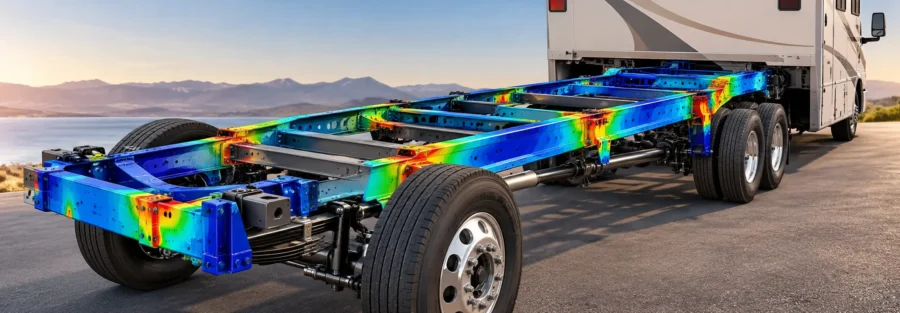
Why Modified RV Chassis Require Structural Validation
Modifying an RV chassis can affect more than the component being changed. Extending a frame, relocating a crossmember, adding equipment mounts, changing a body attachment, or adapting a commercial vehicle chassis for an RV can alter how loads travel through the structure.
A modification that appears acceptable in CAD may introduce local stress concentrations, increase frame deflection, or transfer loads into components that were not designed to carry them.
For RV manufacturers and vehicle engineering teams, finite element analysis (FEA) provides a way to assess these changes before releasing the modified structure for production or physical validation.
The objective is to determine whether the revised chassis meets the defined structural requirements, not simply whether the modified component withstands an individual load.
What Changes Can Affect RV Chassis Performance?
Several common modifications can change the structural response of an RV chassis.
Frame Extensions and Rail Modifications
Extending frame rails to accommodate a different body layout or wheelbase changes the structure’s geometry and load distribution. Depending on the design, the extension may increase bending, alter torsional stiffness, or introduce high stresses near the transition between the original and modified sections.
FEA helps engineers evaluate the revised load path and identify areas that require additional assessment.
Relocated Crossmembers and Mounting Points
Moving crossmembers, suspension attachments, body mounts, or equipment supports changes where forces enter and leave the frame.
A revised mounting location may increase local rail bending or create concentrated loads around brackets and fasteners. The surrounding structure must be included in the analysis to understand these effects.
Additional Equipment and Body Loads
RV conversions may add tanks, generators, batteries, storage systems, lifts, or other equipment. Their mass and mounting locations affect the forces acting on the chassis.
The analysis should account for the actual equipment configuration and its relevant operating loads. Treating added mass as a single uniform load can overlook concentrated forces at mounting interfaces.
Changes to Frame Sections or Materials
Replacing frame members, changing wall thicknesses, or using a different material can affect strength, stiffness, and fatigue performance.
A lighter or stronger component does not automatically make the complete chassis structurally adequate. Engineers must evaluate how the modification affects surrounding members, joints, and load transfer.
How FEA Validates a Modified RV Chassis
1. Establish the Original Chassis Baseline
Where the original chassis model and supporting data are available, engineers can use them to establish baseline structural performance.
This may include reviewing frame geometry, material properties, suspension and body mounting locations, and the original design load cases.
Baseline results provide a useful reference for identifying how the proposed modification changes stress, deformation, and structural stiffness. However, reproducing the original model response does not by itself prove that the original chassis is adequate for every new application.
2. Define the Required Load Cases
A modified RV chassis should be assessed against the loads relevant to its intended configuration and operating conditions.
Depending on the vehicle, these may include:
- Vertical loads from vehicle mass and payload.
- Longitudinal forces associated with braking and acceleration.
- Lateral loads during cornering.
- Torsional loading caused by uneven road surfaces.
- Concentrated loads at suspension, body, and equipment mounting points.
Combined load cases may be necessary where forces act simultaneously. Load magnitudes and combinations should come from applicable design requirements, engineering calculations, test data, or other justified sources rather than arbitrary assumptions.
3. Compare Stress and Deflection Before and After Modification
The FEA model can help engineers compare the original and modified chassis under equivalent load cases.
Key results include stress distribution in frame rails, local stresses around brackets and joints, vertical displacement, torsional deformation, and relative movement at mounting interfaces.
For example, a frame extension may increase deflection near the rear body mounts even if the extension itself remains below the material’s yield strength. A relocated crossmember may reduce deformation in one region while increasing stress elsewhere.
Comparative results help identify these changes and determine whether further design work is needed.
4. Assess Local Connections and Load Transfer
Chassis performance often depends on how individual members are connected.
Welded joints, bolted brackets, crossmember interfaces, and equipment mounts can experience local loading that is not adequately represented by evaluating the main frame rails alone.
The model should represent relevant connections and boundary conditions at a level appropriate to the engineering question. Critical locations may require more detailed local analysis, especially when stress concentrations or fatigue-sensitive welds are involved.
5. Evaluate Durability Where Required
Passing a static strength assessment does not establish that a modified chassis will withstand repeated road loading throughout its intended service life.
Where durability is a requirement, engineers should assess fatigue-sensitive regions using appropriate load histories and material or weld fatigue data. Frame extensions, mounting brackets, and modified joints may warrant particular attention if the modification changes their stress ranges.
The need for fatigue analysis depends on the modification, expected usage, design requirements, and available evidence.
FEA Validation Should Be Supported by Engineering Evidence
FEA is a design assessment tool, not an automatic certification of a modified chassis.
Confidence in the results depends on model quality, material data, load definitions, connection representation, and boundary conditions. Where practical and required, simulation should be supported by physical testing, measured strain or displacement data, inspection findings, or correlation with an established model.
Engineers should also document the modification, assumptions, load cases, acceptance criteria, and results. This provides a traceable basis for reviewing the design and deciding whether further analysis or testing is necessary.
RV Chassis FEA Validation by Caliber Technologies
Caliber Technologies supports structural simulation and engineering analysis for vehicle chassis and frame structures. For modified RV platforms, FEA can help assess frame extensions, relocated mounting points, added equipment loads, structural stiffness, and stress changes caused by design modifications.
The analysis scope should be tailored to the original chassis architecture, proposed changes, intended vehicle configuration, and applicable validation requirements.
Planning an RV chassis modification or evaluating a revised frame design? Contact Caliber Technologies at operations@thecalibertech.com to discuss your structural FEA and validation requirements.