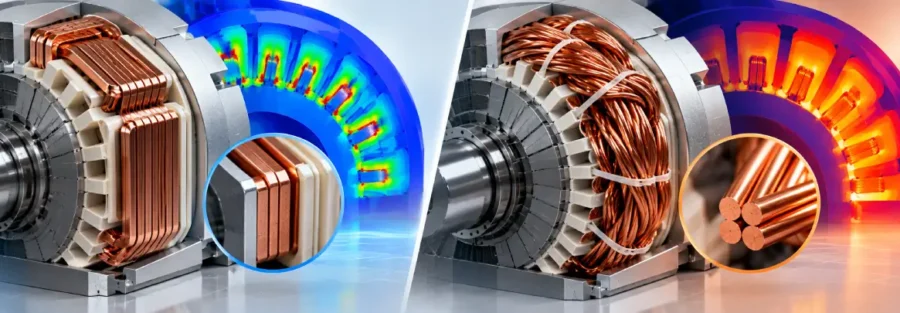
Winding architecture has a direct influence on an electric motor’s electrical performance, thermal behaviour, manufacturability, and packaging. Hairpin and wire-wound motors use different conductor geometries and winding arrangements, which affect slot utilization, resistance, current density, copper losses, heat transfer, and manufacturing processes.
Neither architecture is universally preferable. The appropriate choice depends on motor geometry, operating frequency, current requirements, cooling strategy, available manufacturing processes, and required power density.
Hairpin and Wire-Wound Motor Design Compared
| Design consideration | Hairpin winding | Wire-wound winding |
|---|---|---|
| Conductor geometry | Rectangular or formed conductors | Typically round wire |
| Slot utilization | Potentially high | Depends on winding architecture |
| Manufacturing | Well suited to automated forming and insertion processes | Uses different winding and insertion processes |
| Current density | Depends on conductor geometry and operating conditions | Depends on wire size and winding arrangement |
| Copper losses | Influenced by conductor geometry, resistance, and operating frequency | Influenced by conductor size, resistance, and winding configuration |
| Thermal behaviour | Strongly influenced by conductor and insulation interfaces | Influenced by winding packing and thermal paths |
| Modelling complexity | Can require detailed conductor geometry | Depends on winding architecture |
| Optimization opportunities | Conductor geometry, fill factor, insulation, and layout | Wire size, winding configuration, fill factor, and layout |
The comparison shows why winding selection cannot be based on a single parameter such as slot fill or current density. Electrical, thermal, electromagnetic, and manufacturing requirements must be considered together.
Conductor Geometry and Slot Fill
Conductor cross-section directly affects how effectively copper occupies the available slot area. Formed rectangular conductors can provide high copper utilization when the slot geometry and manufacturing process allow efficient packing.
Wire-wound designs typically use round conductors, with the achievable copper fill factor depending on wire diameter, insulation, winding pattern, and packing arrangement.
A higher copper fill factor can reduce unused slot volume, but the resulting design still needs sufficient electrical insulation and practical manufacturing clearances. Increasing conductor size or copper content without considering thermal paths and manufacturability can create new design constraints.
Resistance, Current Density and Copper Losses
Winding resistance is a fundamental parameter in motor efficiency. For a given current, higher resistance produces greater I²R copper losses, increasing heat generation within the winding.
Conductor cross-section affects resistance and current density. However, current density should not be considered independently of operating frequency, conductor geometry, winding length, temperature, and cooling conditions.
In formed conductors, conductor dimensions and geometry can also influence current distribution and AC losses at higher frequencies. Wire-wound designs have their own electrical constraints based on wire diameter, winding arrangement, and operating conditions.
Electromagnetic analysis can quantify these effects and provide spatially resolved copper-loss data for subsequent thermal analysis.
Thermal Conductivity and Winding Heat Transfer
Copper has high thermal conductivity, but the temperature of a winding is not determined by copper conductivity alone. Heat must travel through insulation, impregnation materials, stator laminations, interfaces, and eventually into the cooling system.
The arrangement and geometry of conductors therefore influence thermal resistance paths. Insulation thickness can affect electrical isolation as well as heat transfer. Closely packed conductors may improve copper utilization while creating different local thermal paths.
Thermal analysis can determine whether the winding develops localized temperature concentrations and whether the available cooling path is sufficient to remove the generated heat.
Winding Hot Spots and Thermal Analysis
Average winding temperature can conceal local hot spots. Regions with higher copper losses or greater thermal resistance can reach significantly higher temperatures than the surrounding winding.
A combined electromagnetic and thermal model can transfer calculated copper losses into the thermal model and predict winding temperature distribution. This allows engineers to examine maximum winding temperature, thermal gradients, heat-flow paths, and hot-spot locations.
The results can then guide changes to conductor dimensions, winding arrangement, insulation, slot geometry, cooling conditions, or operating limits.
Electromagnetic and Thermal Modeling Considerations
The level of model detail should reflect the engineering question. A simplified winding representation may be adequate during early design studies, while detailed conductor geometry can become important when evaluating fill factor, current distribution, AC losses, or localized thermal behaviour.
For hairpin configurations, detailed conductor geometry may be required to represent formed conductors and their spatial arrangement accurately. Wire-wound configurations may require different levels of geometric representation depending on the winding architecture and required outputs.
The electromagnetic model can calculate resistance and copper losses, while the thermal model uses those losses to evaluate temperature. Coupling the two analyses becomes particularly valuable when temperature-dependent resistance significantly affects motor performance.
Manufacturability and Design Optimization
Electrical performance cannot be separated from manufacturing requirements. Conductor geometry must account for forming, insertion, insulation, connections, tolerances, and assembly processes. Wire-wound designs involve their own constraints related to winding operations, conductor size, packing, and process capability.
This creates an important design tradeoff. Increasing copper utilization may improve electrical performance, but excessive geometric complexity can increase manufacturing difficulty. Similarly, reducing insulation thickness may increase available copper area but must remain compatible with electrical insulation requirements.
Simulation allows these variables to be evaluated before finalizing the physical design.
Engineering Outputs and Design Decisions
The objective of comparing winding architectures is to establish measurable differences that can support product decisions.
Electromagnetic analysis can provide resistance, current density, copper loss, current distribution, and loss concentration. Thermal analysis can provide winding temperature, hot-spot temperature, thermal gradients, and heat-flow paths.
These outputs can identify whether a particular conductor geometry creates excessive resistance, current density, copper loss, or thermal loading. Engineers can then modify conductor cross-section, slot fill, winding arrangement, insulation thickness, cooling conditions, or operating parameters.
The correct design is therefore determined by the complete set of electrical, thermal, electromagnetic, and manufacturing requirements rather than by conductor type alone.
Caliber Technologies for Winding Electromagnetic and Thermal Analysis
Caliber Technologies can evaluate winding architectures through integrated electromagnetic and thermal simulation. The analysis can examine conductor geometry, copper fill factor, electrical resistance, current density, copper losses, temperature distribution, thermal resistance paths, and winding hot spots.
Detailed simulation can help determine how changes in conductor geometry and winding configuration influence both electromagnetic performance and thermal behaviour. These results can support design optimization while accounting for practical manufacturing constraints.
This multiphysics approach allows winding design decisions to be based on measurable electrical and thermal behaviour rather than isolated geometric parameters.
Need support with electric motor design or simulation? Email operations@thecalibertech.com to discuss your engineering requirements.
Conclusion
Hairpin and wire-wound motor architectures involve different relationships between conductor geometry, slot utilization, resistance, current density, copper loss, thermal conductivity, insulation, and manufacturability.
A technically sound comparison should therefore avoid treating either architecture as universally superior. The appropriate choice depends on the motor’s operating conditions, electromagnetic requirements, cooling system, manufacturing process, and target power density.
By combining electromagnetic loss analysis with thermal simulation, engineers can identify winding hot spots, quantify copper-loss behaviour, evaluate design tradeoffs, and select a winding configuration that satisfies the specific requirements of the motor application. Caliber Technologies supports this approach through multiphysics analysis focused on measurable design outputs and product-level decisions.