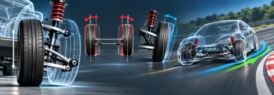
A suspension can have the correct static alignment and still behave very differently once the vehicle starts moving. A wheel that sits at the intended toe and camber angles at ride height may gain camber during compression, lose toe during rebound, or change its steering angle as the suspension moves through its travel.
These changes are not necessarily caused by a defective component. They are often a direct consequence of the suspension geometry.
This is the purpose of suspension kinematics analysis. Engineers use it to understand how wheel position and alignment change as the suspension moves, and how those changes affect tire contact, steering response, cornering behavior, and overall vehicle handling.
The practical engineering question is not simply, “What are the suspension alignment angles?”
It is:
“How do those angles change when the wheel actually moves?”
That distinction becomes important when a vehicle shows handling behavior that cannot be explained by its static alignment alone.
When Static Alignment Looks Right but the Vehicle Still Handles Poorly
Consider a vehicle with the following alignment at normal ride height:
- Front toe: within the design target
- Front camber: within specification
- Steering wheel centered
- Suspension components within dimensional tolerance
Yet during testing, the vehicle may show excessive steering response during suspension compression, inconsistent cornering behavior, or a tendency to pull under certain road conditions.
Looking only at the static alignment does not explain the problem.
The next step is to examine what happens as the suspension moves.
If one wheel gains significantly more toe than the other during compression, the vehicle can develop an unintended steering input. If camber changes rapidly, the tire contact patch can also change as the body rolls and the suspension travels.
This is where a kinematic analysis can reveal a problem that a static alignment check cannot.
What Suspension Kinematics Analysis Actually Measures
Suspension kinematics describes the geometric movement of the suspension system as the wheel moves relative to the vehicle body.
Engineers can evaluate variables such as:
- Wheel toe
- Camber
- Caster
- Wheel center movement
- Track change
- Wheelbase change
- Roll center movement
- Steering angle
- Suspension travel
- Motion ratios
The analysis is usually performed over a range of jounce and rebound, rather than at one static ride-height position.
The resulting curves show how each parameter changes with suspension travel.
For example, a camber-versus-travel curve may show that the wheel gains negative camber during compression. Whether that behavior is desirable depends on the vehicle, suspension architecture, tire characteristics, and handling targets.
There is no universal kinematic curve that is correct for every vehicle.
Why Toe Change Can Create an Unexpected Steering Effect
Toe is one of the most sensitive alignment parameters because a change in toe effectively changes the direction in which the tire is pointing.
Imagine a front suspension moving upward during compression.
As the control arms and steering links rotate through their arcs, the outer steering joint may move inward or outward relative to the vehicle centerline. That movement changes the wheel’s toe angle.
If both wheels experience exactly the same toe change, the vehicle response may differ from a situation where the left and right wheels move differently.
Now consider a vehicle cornering over an uneven road. The outside suspension may be compressed while the inside suspension is closer to rebound.
The two wheels can therefore develop different toe angles.
That difference can create an additional steering effect even though the driver has not changed the steering input.
This is one reason suspension kinematics needs to be considered together with real vehicle operating conditions.
How Camber Changes During Suspension Travel
Camber describes the inclination of the wheel relative to the vertical vehicle reference.
As a suspension moves through jounce and rebound, the control-arm geometry causes the wheel to rotate.
For many independent suspension designs, engineers intentionally develop camber gain to help maintain tire contact during body roll.
For example, when the vehicle corners, the body rolls toward the outside of the turn. The outside suspension compresses while the inside suspension extends.
If the outside wheel gains an appropriate amount of negative camber during compression, it can help compensate for the effects of body roll and maintain a more favorable tire orientation.
However, excessive or poorly controlled camber change can create other issues.
The objective is therefore not simply to maximize camber gain. Engineers need to determine whether the camber curve produces the desired tire behavior across the actual operating range.
A Practical Example: Diagnosing a Steering Change During Suspension Compression
Consider a hypothetical front suspension where the vehicle exhibits a noticeable steering response when one front wheel encounters a bump.
At static ride height, the toe alignment is within the intended range.
An engineer performs a kinematic analysis and finds the following illustrative behavior:
| Suspension position | Toe change |
|---|---|
| 20 mm rebound | +0.02° |
| Ride height | 0.00° |
| 20 mm jounce | -0.08° |
| 40 mm jounce | -0.17° |
| 60 mm jounce | -0.30° |
These values are hypothetical and are included only to demonstrate the diagnostic process.
The analysis shows that toe changes progressively as the wheel moves into jounce.
Now imagine that the outside front wheel enters 40 mm of jounce during a cornering event while the inside wheel experiences a different amount of travel.
The resulting left-right toe difference can introduce an additional steering effect.
The next engineering question is not simply whether -0.30° is “good” or “bad.” The engineer needs to determine whether this kinematic behavior is consistent with the vehicle’s handling requirements and whether it contributes to the observed test behavior.
That requires connecting the suspension model to vehicle-level dynamics.
Why Suspension Geometry Controls These Changes
Toe and camber curves are determined by the three-dimensional geometry of the suspension.
Changing the position of a control-arm inner pivot by a relatively small amount can alter the wheel’s movement path.
The same applies to:
- Control-arm length
- Ball-joint position
- Tie-rod length
- Steering rack position
- Knuckle geometry
- Suspension pickup points
- Ride height
This means that suspension kinematics can often be influenced before any physical component is manufactured.
Engineers can evaluate geometry alternatives digitally and determine how a proposed change affects wheel movement throughout the suspension travel range.
Kinematics Versus Compliance
It is important to distinguish kinematic steer from compliance steer.
Kinematic changes are produced by the geometry of rigid-body suspension movement.
Compliance steer results from deformation of bushings, mounts, links, and other components under applied forces.
In a real vehicle, both effects can occur simultaneously.
For example, a wheel moving through jounce may develop a geometric toe change because of suspension kinematics. At the same time, a lateral tire force may deform a bushing and create an additional toe change.
The final wheel alignment is therefore influenced by both geometry and structural compliance.
This is why K&C and MBD analyses are often valuable when the objective is to understand actual vehicle handling rather than geometry alone.
How Engineers Perform a Suspension Kinematics Study
A kinematic study generally begins with accurate suspension geometry.
The model needs to represent the relevant hard points and steering relationships. The wheel is then moved through a defined range of suspension travel while the resulting changes in alignment and wheel position are calculated.
The resulting curves can be reviewed individually or compared across design alternatives.
A typical investigation may examine:
Suspension travel → toe change → camber change → wheel-center movement → roll-center behavior → handling implications
If the analysis identifies an undesirable trend, engineers can modify suspension hard points and rerun the study.
This makes the process iterative rather than dependent on trial-and-error physical prototypes.
Connecting Kinematics to Vehicle Handling
A kinematic curve by itself does not tell the complete handling story.
The same toe or camber change can have different vehicle-level consequences depending on tire characteristics, suspension stiffness, steering geometry, mass distribution, roll behavior, and driving condition.
This is why the next step can be a multi-body dynamics simulation.
The kinematic characteristics can be incorporated into a vehicle model and evaluated during events such as:
- Constant-radius cornering
- Lane changes
- Braking while cornering
- Bump inputs
- Steering maneuvers
- Split-friction braking
The goal is to determine whether a particular suspension geometry produces the desired vehicle response.
For example, if a suspension generates an unintended steer angle during one-wheel bump, the MBD model can help determine whether that behavior contributes to a directional response observed during testing.
Using FEA When Geometry Is Not the Only Problem
Sometimes a kinematic study shows acceptable behavior, but physical testing still reveals excessive wheel movement.
That can indicate that structural flexibility or bushing compliance is contributing to the response.
FEA can then be used to evaluate control arms, knuckles, brackets, steering components, and other structural parts.
The combined workflow can become:
Suspension geometry → kinematics → MBD → component FEA → compliance characteristics → vehicle response
This approach helps engineers separate geometric effects from structural effects.
It also prevents a common mistake: changing suspension hard points to compensate for a problem that actually originates from component stiffness.
How Engineers Optimize Suspension Kinematics
Optimization should start with the vehicle behavior that needs to be improved.
Suppose testing shows excessive toe change during jounce.
The engineer can investigate whether changes to the steering-link geometry, control-arm pickup points, or other hard points reduce the unwanted movement.
But the modification cannot be evaluated only against toe.
A geometry change that improves toe may alter camber gain, roll-center movement, wheel travel, steering effort, or packaging.
This makes suspension kinematics a multi-variable engineering problem.
A good design is therefore not the one with the smallest change in one alignment parameter. It is the one that provides an appropriate combination of wheel control, handling response, ride behavior, packaging, and structural requirements.
Correlating Kinematic Analysis With Physical Testing
Simulation results should be compared with physical measurements when prototypes become available.
Suspension kinematics can be measured using suspension rigs, wheel alignment measurement systems, motion capture systems, or other suitable instrumentation.
The measured toe, camber, and wheel-center movements can then be compared with the simulation.
If the curves do not match, engineers can investigate whether the difference comes from manufacturing tolerances, actual hard-point locations, component deformation, bushing behavior, measurement uncertainty, or assumptions in the model.
This correlation is particularly useful because small geometric differences can produce measurable changes in suspension behavior.
How Caliber Technologies Can Support Suspension Kinematics Analysis
Suspension kinematics analysis is most useful when it is connected to the larger vehicle development process.
Caliber Technologies can apply suspension kinematics, K&C analysis, multi-body dynamics, FEA, and vehicle-level simulation to investigate how suspension geometry affects wheel alignment and vehicle response.
The objective is to move beyond static alignment targets and understand what the wheel actually does as the suspension moves and the vehicle experiences real driving conditions.
By evaluating geometry digitally, engineering teams can identify problematic toe and camber behavior earlier, compare suspension concepts, and make targeted changes before relying heavily on physical prototype testing.
Conclusion
A suspension’s static alignment tells only part of the story.
Once the vehicle moves, suspension geometry causes the wheels to follow three-dimensional paths. Those paths determine how toe, camber, wheel position, and other characteristics change throughout suspension travel.
For engineers investigating unexpected steering response or handling behavior, the important question is therefore not simply whether the suspension is correctly aligned at ride height. It is how the wheel behaves when the suspension actually moves.
Suspension kinematics analysis provides that missing view.
When combined with K&C analysis, MBD, FEA, and physical correlation, it gives engineers a way to connect suspension hard-point geometry with actual vehicle behavior and make targeted design changes before problems become expensive prototype or validation issues.
Frequently Asked Questions
What is suspension kinematics analysis?
Suspension kinematics analysis evaluates how the wheel and suspension components move relative to the vehicle body as the suspension travels through jounce and rebound.
Why does toe change when the suspension moves?
Toe changes because suspension links and steering components rotate through their geometric paths as the wheel moves. The positions of suspension hard points, control arms, steering links, and the knuckle determine the resulting toe curve.
Why is camber change important?
Camber change affects the orientation of the tire relative to the road. Engineers analyze the camber curve to understand how the tire behaves during suspension travel and body roll.
What is the difference between kinematic steer and compliance steer?
Kinematic steer results from suspension geometry during movement. Compliance steer results from deformation of suspension components, bushings, mounts, and other flexible elements under load.
How does suspension kinematics affect vehicle handling?
Changes in toe, camber, wheel position, and other geometric characteristics can influence tire behavior and steering response. Their vehicle-level effect depends on the complete suspension, tire, steering, and vehicle dynamics system.
Can suspension kinematics be optimized before building a prototype?
Yes. Engineers can evaluate suspension hard-point alternatives using digital kinematic and multi-body dynamics models before physical prototypes are built.
How is suspension kinematics validated?
Simulation can be correlated with suspension rig measurements, wheel alignment measurements, motion measurements, and vehicle testing to verify that the modeled suspension movement matches physical behavior.