A truck chassis can have acceptable material strength, reasonable dimensions, and a seemingly adequate FEA result, yet still develop excessive stress around a bracket, cross-member, suspension mount, or frame transition. In many cases, the problem is not simply that the chassis is too weak. The more important question is whether the load path through the structure has been understood correctly.
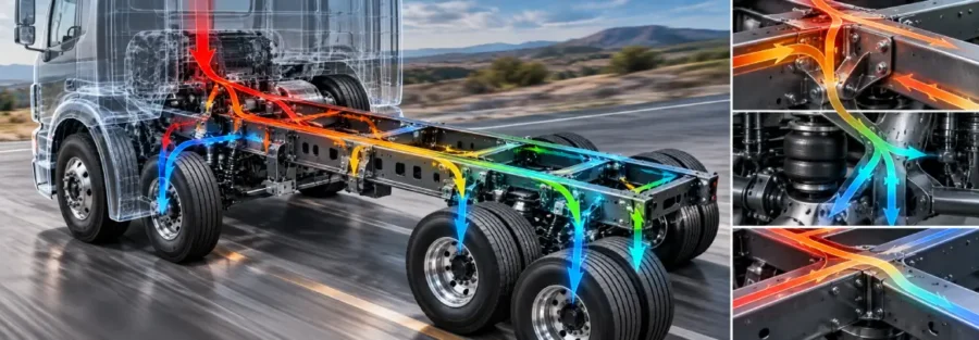
When a truck moves over an uneven road, the load does not travel through the frame as one simple vertical force. Tire forces pass through the wheels and suspension, enter the frame at several locations, interact with cross-members and brackets, and eventually distribute through the complete chassis structure.
Understanding that path is essential when engineers are investigating unexpected deformation, local stress concentrations, frame twist, or durability problems.
This is where truck chassis load path analysis becomes useful. Instead of looking only at the highest stress on an FEA contour, engineers trace how forces and moments enter the chassis, how the structure carries them, and where the load path changes because of geometry, stiffness, joints, or connections.
What Is a Chassis Load Path?
A load path is the physical route through which an applied force or moment is transferred through a structure.
For a truck, consider a vertical road input at one wheel. The force begins at the tire contact patch and moves through the wheel and hub into the suspension. From there, it reaches suspension brackets or frame-mounted components before entering the frame rails.
The frame then distributes the load through longitudinal members, cross-members, brackets, and other structural connections.
A simplified representation is:
Road surface → tire → wheel/hub → suspension → mounting points → frame → cross-members → opposite frame structures
That representation is useful, but it is not complete for every vehicle architecture. Longitudinal braking forces and lateral cornering forces follow different paths, while combined events can create simultaneous bending and torsional loading.
The actual load path depends on the suspension layout, frame architecture, joint stiffness, mounting strategy, payload distribution, and vehicle operating condition.
Why Engineers Need to Understand the Load Path
Imagine a truck chassis that develops cracks near a suspension mounting bracket.
One approach is to increase the bracket thickness and rerun the FEA.
That may reduce the local stress, but it does not necessarily solve the underlying problem. If the bracket is receiving more load than expected because of the surrounding frame stiffness, the additional material may simply redirect the force into another region.
A better investigation begins with the question:
Why is this location carrying this much load?
Engineers can then examine the surrounding structure and determine how the force enters the frame, how it is distributed, and where the load path becomes concentrated.
This is particularly important when modifying an existing chassis. Adding a cross-member, changing a bracket, relocating a suspension mount, or modifying frame-rail stiffness can change the distribution of forces throughout the structure.
A Road Load Does Not Become a Frame Load Automatically
One of the common mistakes in structural analysis is treating a measured or calculated wheel load as if it can simply be applied directly to the chassis at one convenient location.
The wheel force is an input to the suspension system. The suspension geometry determines how that force is transferred into the frame.
Consider a vertical wheel load. Depending on the suspension design, the load may enter the chassis through multiple control-arm mounts, spring seats, shock mounts, trailing-arm attachments, or other interfaces.
The frame therefore sees a combination of forces and moments rather than simply receiving the original tire force unchanged.
This distinction becomes particularly important when developing FEA boundary conditions.
If the load is applied at the wrong location or with the wrong force and moment distribution, the FEA model may produce a stress pattern that looks technically detailed but does not represent the actual vehicle.
Concrete Failure Case: Cracks Around a Rear Suspension Bracket
Consider a hypothetical heavy-duty truck that begins developing fatigue cracks at the weld connecting a rear suspension bracket to the frame rail after extended operation on mixed roads.
The initial inspection shows that the cracks are concentrated near the forward edge of the bracket. The frame rail itself has not experienced a global structural failure, and a basic static FEA study shows that the overall chassis stress remains below the material’s nominal allowable stress.
At first glance, the bracket may appear to be the weak component.
However, the engineering investigation needs to answer a different question:
Why is this bracket receiving a concentrated load in the first place?
Suppose vehicle measurements and MBD analysis indicate that a severe road event generates an approximately 35 kN vertical suspension reaction at the rear suspension assembly. The reaction is transferred into the chassis through two mounting regions separated along the frame.
For illustration, the calculated reactions are:
- Forward suspension attachment: 21 kN
- Rear suspension attachment: 14 kN
- Total vertical reaction: 35 kN
These values are hypothetical and are not design limits or measurements from a Caliber project.
The first FEA model applies the total 35 kN load directly to a simplified suspension mounting region. The global frame response looks reasonable, but the local bracket stress does not correlate well with the physical crack location.
The engineering team then examines the actual suspension geometry and replaces the simplified loading with the individual forces and moments generated at the suspension interfaces.
The result changes significantly.
The forward bracket is not simply carrying 21 kN vertically. Because the suspension reaction acts through a location offset from the frame attachment, it also introduces a local moment. The bracket therefore experiences a combination of vertical force, longitudinal force, and moment loading.
The detailed FEA now shows elevated stress around the bracket-to-frame transition, particularly near the weld toe where the geometry creates a local stiffness change.
This provides a more credible explanation for the field failure.
What the Investigation Reveals
The important finding is that the crack was not necessarily caused by insufficient material strength in the bracket itself.
The problem was a concentrated load path.
The suspension was transferring a significant portion of the road-induced reaction into one region of the frame. The bracket then transferred that load into the frame rail over a relatively small area.
The load path can be represented as:
Road input → tire → suspension → suspension bracket → bracket weld → frame rail → cross-member/frame structure
The detailed analysis shows that the bracket and its connection were acting as a transition between two regions with substantially different stiffness.
That stiffness change concentrated the structural response near the weld.
What Would Happen If Engineers Simply Made the Bracket Thicker?
This is where load-path analysis becomes important.
Suppose the first proposed solution is to increase the bracket thickness.
The local bracket stress may decrease, but the increased stiffness can change the way the load enters the frame. The additional load may then be transferred into the adjacent frame rail or weld region.
A better design investigation would compare several changes:
- Increase bracket stiffness
- Increase the load-transfer area
- Improve the bracket-to-frame transition
- Modify the cross-member connection
- Redistribute the suspension reaction between structural members
The preferred engineering solution should be determined from the complete structural response, not simply from whichever modification produces the lowest stress at the original crack location.
Why This Matters for FEA
This failure case illustrates a common issue in chassis analysis.
A model can produce a technically correct stress contour for the loads that were applied, while still failing to represent the actual vehicle if the load application itself is incorrect.
The important sequence is:
Field failure → identify operating event → determine suspension reactions → trace load path → calculate structural response → identify local cause → modify design → validate
That is much closer to how a real chassis durability investigation is performed than simply running a maximum-load static FEA.
Note: The truck, crack location, load values, and reactions in this example are hypothetical and should be presented as an illustrative engineering failure investigation, not as a documented Caliber project or field failure.
Different Driving Events Create Different Load Paths
The load path changes depending on what the truck is doing.
During vertical road excitation, the dominant loads may enter through the suspension mounting points and create bending and local frame loads.
During braking, longitudinal tire forces create additional reactions through the suspension and frame attachments. The resulting chassis response can involve both longitudinal loading and local moments.
During cornering, lateral forces introduce another load-transfer mechanism. Because the left and right suspension systems are loaded differently, the frame can experience significant torsion in addition to bending.
A combined braking and cornering event can be even more demanding because several load components act simultaneously.
This is why a chassis should not be evaluated only using an isolated vertical load if the intended operating environment includes significant braking, cornering, towing, or uneven-road operation.
How Engineers Trace the Load Path in FEA
A useful load-path investigation usually begins with a global structural model.
The objective at this stage is not to capture every weld or small fillet. It is to understand how the overall chassis responds.
Engineers examine:
- Frame-rail forces and reactions
- Cross-member load transfer
- Suspension mounting reactions
- Global bending
- Torsional deformation
- Local stiffness changes
- Relative movement between connected structures
Once the global behavior is understood, areas with significant load concentration can be investigated using more detailed models.
This creates a useful distinction between global load transfer and local stress analysis.
A detailed local model may show a very high stress around a bracket corner, but without understanding the global load entering that bracket, it can be difficult to determine whether the result represents a genuine structural issue or a modeling artifact.
Worked Example: Following a Rear Suspension Load
Consider a simplified hypothetical truck with a rear suspension that transfers vertical road loads into the chassis through two frame-mounted suspension brackets.
Assume a simulated road event produces a vertical reaction of 30 kN at the suspension assembly.
For illustration, suppose the suspension geometry distributes this reaction approximately between two frame attachment regions:
- Front attachment: 18 kN
- Rear attachment: 12 kN
These values are hypothetical and are intended only to demonstrate the load-path concept.
The 30 kN wheel or suspension reaction should not automatically be applied as a single 30 kN force to one frame bracket.
Instead, the engineer needs to understand how the suspension transfers the load.
If the attachment points are separated longitudinally, the force distribution can also generate a moment about the frame structure.
For example, assume the two attachment points are separated by 0.8 m.
The difference in reaction between the two locations contributes to the local load state, while the suspension geometry and applied forces determine the complete reaction system.
In an actual MBD model, engineers would obtain the forces and moments at each interface directly from the suspension response. These interface loads could then be transferred into the chassis FEA model.
The important result is not simply that the chassis receives 30 kN.
The important result is understanding where that load enters, how it is divided, and what forces and moments it creates as it travels through the frame.
When a Load Path Suddenly Changes
A particularly important issue occurs when the stiffness of the chassis changes abruptly.
For example, consider a frame rail connected to a relatively stiff cross-member. If the cross-member is significantly stiffer than the surrounding structure, it may attract a larger portion of the load.
This can be beneficial if the structure was intentionally designed to carry that load. However, it can also create local stress concentrations around the connection.
The same effect can occur when engineers add reinforcement to solve a local fatigue problem.
The reinforcement may reduce deformation at the original location while increasing stiffness nearby. As a result, the load may shift into another bracket, weld, or frame section.
This is why structural modifications should be evaluated at the system level rather than only at the location being reinforced.
Load Path Analysis and Chassis Torsion
Truck chassis torsion is another situation where load paths become particularly important.
Consider a truck traveling over an uneven road where one rear wheel encounters a higher road input than the opposite wheel.
The left and right suspension reactions are no longer equal. The frame must accommodate the difference.
That creates a torsional response through the chassis.
Cross-members, frame rails, suspension brackets, and body mounts all contribute to how that torsional load is distributed.
A chassis with insufficient torsional stiffness may experience excessive twist. Conversely, significantly increasing local stiffness can alter how loads are transferred into neighboring components.
This makes torsional stiffness and load-path behavior important considerations when evaluating frame modifications.
Connecting MBD to Chassis FEA
This is where multi-body dynamics can provide useful information that a standalone structural model cannot easily generate.
An MBD model can simulate the suspension and vehicle response over representative road inputs. Instead of assuming that the chassis sees a predefined force, engineers can calculate the forces and moments generated at the actual suspension interfaces.
Those interface loads can then be transferred into the chassis FEA model.
The workflow becomes:
Vehicle event → tire forces → suspension response → interface reactions → chassis FEA → structural stress and deformation
This connection is particularly useful when the objective is to understand a real vehicle problem rather than evaluate an arbitrary static load case.
For example, if a chassis experiences excessive stress during a rough-road event, MBD can help determine whether the issue is caused by the road input, suspension characteristics, wheel load transfer, or another vehicle-level interaction.
FEA can then determine how those loads affect the structure.
What Engineers Look For in a Load Path Study
A load-path investigation should answer several practical questions.
Where does the load enter the chassis?
The answer depends on the suspension and mounting architecture.
How does the load divide between structural members?
The distribution is influenced by stiffness and geometry.
Where does the load change direction?
Changes in direction often occur at brackets, joints, cross-members, and frame transitions.
Where does the structure become locally overloaded?
This is where detailed FEA and stress analysis become important.
Does a proposed reinforcement improve the original problem or simply move the load elsewhere?
This final question is particularly important during design optimization.
From Load Path to Design Improvement
Once engineers understand the load path, design changes become more targeted.
If a bracket is overloaded because the surrounding structure is too flexible, increasing bracket thickness alone may not be the best solution.
If a cross-member is attracting excessive load, its stiffness and connection geometry may need to be reviewed.
If a frame transition creates a sharp stiffness change, modifying the geometry may provide a better load transfer than simply adding material.
In other cases, the solution may involve changing suspension mounting locations or improving the distribution of loads between structural members.
The objective is to create a controlled load path, not simply a heavier structure.
Validating the Predicted Load Path
A simulation-based load-path assessment should ideally be correlated with physical measurements.
Strain gauges can be placed at critical frame locations to measure structural response during representative driving events. Suspension forces or other interface loads can also be measured where suitable instrumentation is available.
Comparing measured strain or reaction forces with simulation results can reveal whether the assumed load path matches actual vehicle behavior.
If the measured response differs significantly from the model, engineers can investigate assumptions involving joint stiffness, boundary conditions, suspension characteristics, structural flexibility, or load application.
This correlation is valuable because a structurally detailed FEA model is only as useful as the loading and boundary conditions supplied to it.
How Caliber Technologies Can Support Load Path Analysis
Truck chassis development often requires more than a conventional static FEA study. Understanding how road loads move through the suspension and frame requires vehicle-level and structural-level analysis to work together.
Caliber Technologies can apply multi-body dynamics, structural FEA, load-case development, chassis analysis, and virtual validation to investigate how forces and moments travel through vehicle structures.
The objective is to identify the actual structural load path, locate regions where loads become concentrated, and use that information to guide chassis design changes.
For engineering teams dealing with frame stress, bracket failures, excessive deformation, torsional behavior, or durability concerns, load-path analysis can provide the connection between the observed problem and the structural change required to address it.
Conclusion
A truck chassis does not experience road loads as isolated forces applied directly to a frame. Those loads enter through the tires and suspension, divide between mounting points, travel through frame rails and cross-members, and create combinations of bending, torsion, and local loading.
Understanding that process is the purpose of truck chassis load path analysis.
When engineers trace the load from the road input through the suspension and into the structure, FEA becomes more than a stress-contour exercise. It becomes a way to understand why a particular location is carrying a particular load and what needs to change to improve the design.
The most effective chassis development process therefore connects real vehicle events, suspension loads, structural load paths, FEA, and physical validation. That connection helps engineers solve the actual structural problem rather than simply treating the visible symptom.
Frequently Asked Questions
What is truck chassis load path analysis?
Truck chassis load path analysis determines how forces and moments generated during vehicle operation enter and travel through the chassis structure. It helps engineers identify load concentrations and understand the structural behavior behind local stress or deformation.
Why is load path important in truck chassis FEA?
Incorrect load application can produce unrealistic stress distributions. Understanding the actual load path allows engineers to apply forces and moments at representative suspension and structural interfaces.
How are chassis loads generated?
Chassis loads can come from physical road-load measurements, instrumented vehicle testing, proving-ground data, or vehicle and multi-body dynamics simulations.
How does MBD help with chassis load path analysis?
MBD can simulate the suspension and vehicle response to road, braking, cornering, and other events. It can provide forces and moments at chassis interfaces that can subsequently be used in structural FEA.
What causes load concentrations in a truck chassis?
Load concentrations can result from changes in stiffness, brackets, joints, cross-member connections, suspension mounts, frame transitions, geometry changes, or uneven load distribution.
Does adding reinforcement always reduce chassis stress?
No. Reinforcement can reduce stress locally while transferring additional load into adjacent structures. The entire load path should therefore be evaluated after a structural modification.
How can engineers validate a predicted chassis load path?
Engineers can compare simulation results with strain measurements, interface load measurements, component testing, or vehicle-level durability testing. Correlation helps determine whether the simulated load transfer represents actual vehicle behavior.