
Modern vehicles are marvels of integration and performance, where every cubic centimeter of space beneath the hood is leveraged for functionality, efficiency, and serviceability. In this tightly packaged environment, managing heat is not just an engineering challenge—it’s a fundamental requirement for safety, reliability, and performance. Underhood Thermal Management (UTM) aims to ensure that all components—from powertrains and batteries to sensors and wiring harnesses—operate within optimal temperature ranges, regardless of external conditions or driving behavior.
Computational Fluid Dynamics (CFD) has revolutionized how engineers approach this intricate balance. By numerically simulating airflow and heat transfer, CFD allows design teams to visualize thermal behavior early in the development process, reducing reliance on costly prototypes and test iterations.
The Thermal Challenge Beneath the Hood
The underhood region of a modern vehicle is a dynamic thermal ecosystem. Multiple heat sources—combustion engines, electric motors, exhaust manifolds, batteries, and electronic control units—all generate heat that must be dissipated efficiently. Convection from airflow, conduction through metallic structures, and radiation from hot surfaces interact in complex ways.
Designers must answer several critical questions:
- How efficiently is cool ambient air drawn into the engine bay?
- Are nearby electronics at risk of overheating under heavy load or idle conditions?
- Do transient events, such as stop-and-go traffic, cause local hotspots or heat soak?
Traditional physical testing can capture some of these details, but only after prototypes exist. By contrast, CFD models can predict these behaviors in advance, guiding design decisions that mitigate thermal issues before they become real-world problems.
How CFD Enables Predictive Thermal Management
At its core, CFD solves the governing equations of fluid motion (Navier–Stokes equations) combined with energy conservation and radiation models. This enables engineers to predict airflow patterns, surface temperatures, and heat fluxes throughout the underhood environment.
In a typical CFD workflow for underhood thermal management, the process begins with geometry preparation. Engineers construct a highly detailed three-dimensional model of the vehicle’s underhood region, capturing the complex arrangement of engine components, ducts, radiators, fans, and surrounding structural elements. This digital representation serves as the foundation for all subsequent analysis, ensuring that every surface and passage contributing to thermal behavior is accurately captured.
Once the geometry is complete, the model undergoes mesh generation. In this stage, the fluid and solid domains are divided into a vast number of discrete elements, sometimes running into the millions. This mesh acts as the computational canvas upon which the governing equations of fluid flow and heat transfer are solved. The level of mesh refinement is especially critical in regions where steep gradients of temperature or velocity occur, such as near exhaust manifolds, fan blades, and coolant passages.
With the mesh established, boundary conditions are then applied to define how the system interacts with its surroundings. These include specifying the airflow entering through inlets, modeling the performance characteristics of cooling fans, assigning heat generation rates to various components such as engines or batteries, and setting the ambient temperature conditions that reflect real-world operating environments. These parameters collectively determine the thermal and aerodynamic context in which the simulation will operate.
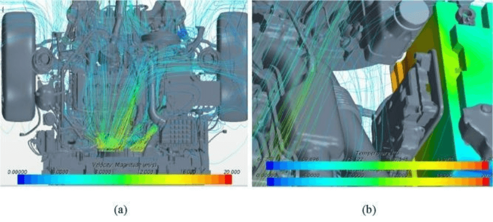
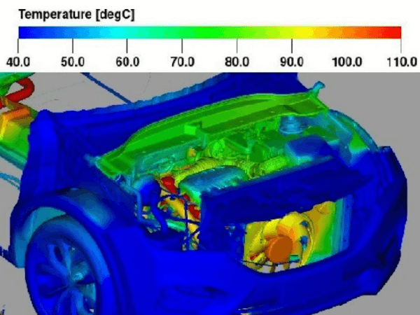
The final phase involves solution and post-processing. Engineers perform either steady-state or transient simulations depending on whether they seek long-term thermal equilibrium insights or time-dependent behavior, such as heat soak following engine shutdown. The results are then analyzed to visualize airflow patterns, temperature distributions, and critical hotspots within the underhood space. Through this detailed evaluation, designers can identify inefficiencies, validate cooling strategies, and refine component placement—ultimately achieving a well-balanced, thermally resilient design.
By integrating CFD results with optimization algorithms, engineers can explore “what-if” scenarios, such as redesigning vent openings, adjusting fan speeds, or relocating heat-sensitive components. This process turns CFD from a diagnostic tool into a design driver.
Applications Across Powertrain Technologies
Internal Combustion Engine (ICE) Vehicles: CFD helps balance airflow between cooling systems and intake ducts, preventing recirculation zones that raise engine bay temperatures. It also aids in designing insulation shields, undertrays, and grille shutters for improved aerodynamic and thermal efficiency.
Electric and Hybrid Vehicles (EV/HEV): For electrified platforms, UTM focuses on maintaining battery pack and inverter temperatures within narrow safety limits. CFD helps simulate coolant flow paths, assess thermal runaway risks, and optimize cabin- and component-cooling integration when waste heat profiles differ dramatically from traditional engines.
Benefits Beyond the Prototype Phase
CFD-driven UTM offers multiple advantages:
- Reduced Development Time: Enables virtual testing across dozens of thermal scenarios before hardware exists.
- Lower Costs: Minimizes physical prototype iterations and expensive wind tunnel testing.
- Improved Reliability: Early detection of thermal risks leads to longer component lifespan and fewer field failures.
- Enhanced Vehicle Efficiency: Optimized heat rejection systems contribute to better fuel economy, range, and comfort.
As vehicle complexity grows, the synergy between digital simulation and physical validation forms the backbone of agile engineering workflows. At Caliber Technologies, we combine engineering experience, advanced CFD modeling, and deep knowledge of vehicle thermal systems to deliver actionable insights for thermal analysis and optimization. Our simulation-driven approach ensures that every airflow path, and every design aspect contribute to an optimum packaging as well as cooling performance.