Designing the structural architecture of a towable RV is an exceptionally complex engineering undertaking—far more sophisticated than the traditional “rule-of-thumb” approaches historically used across the industry. Many manufacturers have historically relied on legacy frame geometries that merely survive the warranty period rather than performing reliably across the full lifecycle.
At Caliber Technologies, this problem is addressed through the application of automotive-grade finite element analysis (FEA), multibody dynamics (MBD), and durability simulation workflows typically applied to passenger vehicles, commercial chassis, and critical automotive structures. By integrating these advanced methods, Caliber is helping RV manufacturers transition from intuition-driven design to data-driven, simulation-led engineering that ensures long-term reliability under real-world loading.
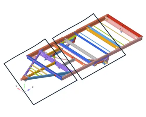
From a structural engineering standpoint, the RV frame can be decomposed into three critical subsystems:
- The A-Frame (Front Tongue Structure)
- The Suspension and Intermediate Frame Structure
- The Rear Hitch and Rear Overhang Structure
Each subsystem must be carefully analyzed and optimized, both individually and as part of the global structure. Caliber’s engineering process brings advanced modeling, accurate load prediction, and detailed stress/fatigue analysis into each stage of development—ensuring that engineering decisions are backed by quantitative evidence.
1) The A-Frame: Primary Load Path for Towing, Tongue Weight, and Global Bending
The A-frame is the primary structural link between the tow vehicle and the RV. It carries:
- Static tongue weight
- Dynamic road inputs from potholes, dips, and trailer pitching
- Longitudinal loads from braking and acceleration
- Torsional inputs from uneven tire paths
- Vibration and high-cycle fatigue loads transmitted through the hitch assembly
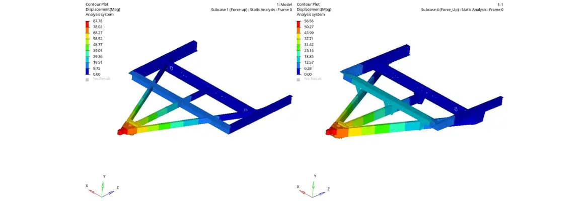
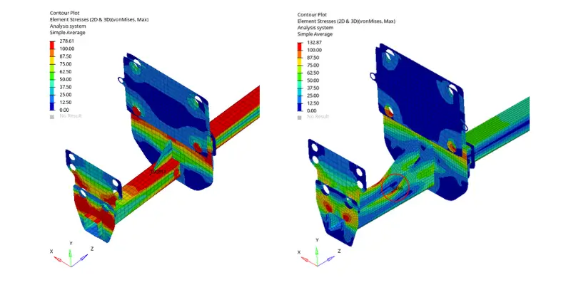
Because these loads act simultaneously and nonlinearly, Caliber applies detailed structural simulations—both linear and non-linear—to evaluate buckling, yielding, fatigue sensitivity, and potential failure points. This includes:
- Weld modeling with heat-affected zones
- Local stiffener effectiveness
- Load path optimization between coupler, jack tower, and main rails
- Tongue weight distribution analysis using MBD-derived reaction forces
Caliber Technologies’ capability in automotive-level load generation enables accurate prediction of worst-case loading conditions. Suspension layout and axle position strongly influence global bending; Caliber uses full-vehicle simulation to quantify how design choices amplify or reduce stress in the A-frame.
This approach ensures that the A-frame is not merely sized for static load rating, but engineered for road-induced fatigue, shock events, and lifecycle durability, preventing field failures common with legacy RV frame designs.
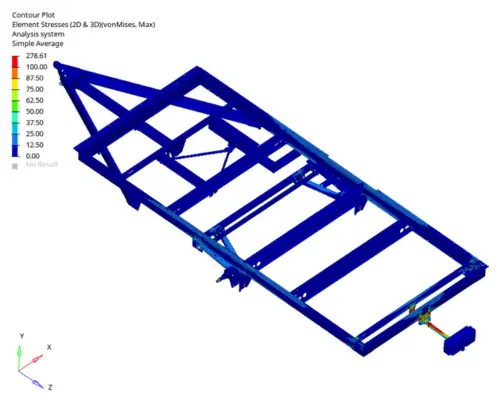
2) Suspension Zone & Primary Frame Rails: The Structural Region That Absorbs the Road
The suspension system and its attachment to the frame take on the most demanding and unpredictable structural loads on the entire RV. Unlike the predominantly quasi-static A-frame loads, suspension-induced forces are Dynamic, Multi-axial, Broadband in the frequency domain and highly sensitive to terrain and driving speed. Caliber Technologies brings extensive expertise from automotive chassis development to model:
- Vertical impacts from potholes
- Lateral sway forces
- Longitudinal shock loads during braking or wheel hop
- Frame torsion from uneven road articulation
- Fatigue damage using PSD-based vibration fatigue analysis
This region is particularly vulnerable to failure when engineering rigor is not applied. Common real-world RV issues include:
- Cracking near suspension hanger welds
- Local buckling of thin-wall rectangular tubes
- Stress risers at poorly reinforced equalizer brackets
- Propagation of fatigue cracks into main rails
Caliber uses a combined MBD + FEA durability workflow to address these challenges. MBD simulations generate realistic road loads, which are then applied as input into a detailed finite element model of the frame. This allows robust prediction of Fatigue life, Local HAZ sensitivity, Weld behavior, and load-sharing between crossmembers. These automotive-grade capabilities empower suspension and frame designs that are structurally efficient, manufacturable, and durable across the full service life—not just the warranty period.
3) Rear Hitch & Overhang: High-Bending-Moment Cantilevers for Cargo and Accessories
The rear overhang is often the least engineered region in traditional RV designs despite being subjected to enormous structural demands. Modern consumers expect:
- E-bike racks
- Cargo trays
- Generators
- Spare tire carriers
- Accessory mounts
These produce large static and dynamic bending moments because the load sits far behind the suspension attachment—a classic cantilever problem with amplified stress.
Caliber’s simulations clearly show that even a modest 200–300 lb rear accessory load can create bending moments comparable to those at the A-frame. When the rear structure is not properly engineered, typical issues include:
- Vertical frame bending and permanent set
- Cracks near rear crossmembers
- Torsional buckling of thin-wall tubes
- Weld failures at hinge brackets
- Excessive rear bounce and modal amplification
Using nonlinear FEA, Caliber evaluates rear-hitch and overhang structures under:
- Static accessory loads
- Dynamic shock loads
- Trailer pitching and heaving
- Lateral offset loading
- Multi-modal vibration
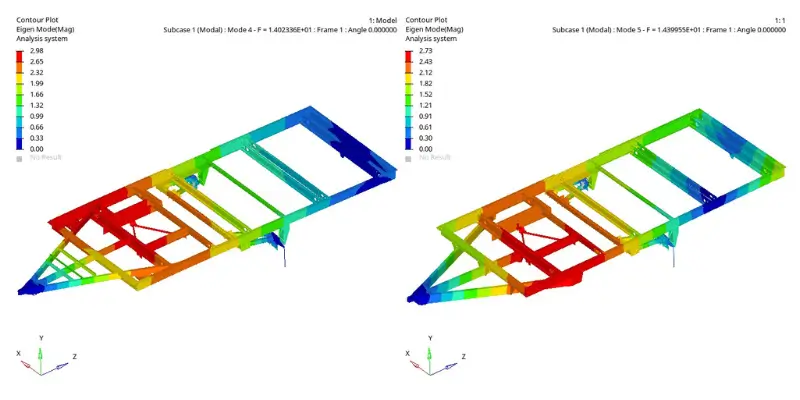
Caliber also applies modal analysis to ensure that rear-mounted accessories do not resonate with frame modes—an often overlooked phenomenon that accelerates fatigue failure.
Conclusion
Modern RV frame design demands far more than traditional metal sizing or incremental tweaks—it requires a holistic, simulation-led approach that accurately predicts real-world performance across the entire life of the vehicle. The A-frame, suspension, and rear hitch form the structural backbone of the RV; each has its own engineering complexities, failure modes, and design constraints.
By applying advanced FEA, dynamic load modeling, and durability engineering, Caliber Technologies ensures that every critical structure within the RV is engineered with the same rigor used in high-volume automotive chassis development. This elevates structural performance beyond warranty compliance toward true lifecycle integrity.